Connecting the front panel of the computer to the motherboard. Computer system unit The process of connecting the front panel of the system unit case
The system unit is, in fact, the computer itself. It is also called “system specialist”. The system unit contains vital devices for processing and storing information - a laser disk drive (or disk drive), a power supply, both the devices themselves and the internal space of the system unit.
Operating computer components generate a significant amount of heat (especially the processor and video card), which is why there are holes in the case designed for air flow, and fans inside remove heat from the processor and video card. Most of the components are located directly on a large electronic board - the motherboard. The power supply, optical drive (disk drive) and hard drive are connected to the motherboard using connectors.
Front panel of the system unit
On the front panel of the system unit there are:
- large power button;
- small general reset button;
- power-on indicator (light) and hard drive operation indicator;
- card reader (in older models – floppy disk drive);
- universal USB connectors;
- connectors for connecting headphones and microphone.
Some models of system units may not have headphone and microphone jacks. They will definitely be on the back of the system unit.

The Reset button is designed to completely reset the computer if it does not respond to any actions at all. In this case, clicking Reset helps to emergency reboot the computer. Most often, the Reset button is recessed into a small hole, and to get to it you will need an unbent paper clip or a match.
Rear panel of the system unit
On the rear panel of the system unit we will see a socket for connecting a network cable, a power supply fan grille and a vertical panel with connectors:
- purple connector for connecting a keyboard;
- green connector for connecting a mouse;
- large red LPT parallel port connector;
- 9-pin serial COM connector;
- VGA connector of the built-in blue video card for connecting a monitor;
- several USB connectors;
- connector for connecting to the network;
- connectors for connecting a microphone (orange), speakers or headphones (green), line input (blue).
Separately below and horizontally, there are connectors for the so-called external video card. A long white connector for connecting a monitor via a digital interface (DVI), which provides a higher quality image.
A narrow black connector for connecting a monitor via the HDMI digital interface, which transmits sound along with the image. Allows you to get the highest quality picture and sound. It is designed to connect a variety of video devices with this interface - TVs, monitors, etc...
Again the familiar blue VGA connector. In fact, it is already outdated, and previously it was the main one for connecting a monitor, but it is still used.

Cheap office computers may not have an external video card, and then the monitor is connected to a connector on the vertical panel. Here we looked at the main elements that are present in any system unit. Depending on the electronic expansion boards, additional connectors may be found.
System unit case
The system unit case is made of thin steel, aluminum or plastic. The most widespread are vertical system units, as they are called “towers,” due to the larger space for installing additional components (expandability) and better air circulation inside, which is important for cooling operating components. Horizontal system units (Desktop) have practically disappeared from the scene; they were previously popular in offices and educational institutions.
Share.When replacing the motherboard or computer assembly, the user quite often encounters the problem of connecting the front panel of the system unit. Perhaps this is the only moment that causes certain difficulties. The best option is when you have a manual or connection diagram on hand. This information can be found through the official website and download this manual for the board.
As a rule, the connection of controls and connectors of the front panel of the case begins when the motherboard is already fixed in the case. The controls are a bundle of wires with connectors Power LED- and Power LED+ (computer status indicator), Power SW (power key), Reset SW (forced reboot button) and HDD LED-, HDD LED+ (drive activity indicator). All motherboard manufacturers use their own designations. For example, PANEL in ASUS, F_PANEL in GIGABYTE, JFP1 in MSI boards; PANEL1 in ASRock.
The approximate diagram of connecting the front panel to the motherboard is as follows, but depending on the manufacturer it may differ slightly.
| Power LED- | Power SW | Power SW | |
| HDD LED+ | HDD LED- | Reset SW |
Each cable has its own port. If the connection is incorrect, the computer simply will not start. This is what the place to connect the main elements looks like. Below there is a table from which you can determine in what order you need to connect the wires. There are two rows of pins for power, so all connections must be exactly as shown in the table.

The same connection diagram is in the manual for the motherboard, but it is often not entirely clear how to connect due to the lack of step-by-step photographs.
To connect the front audio connectors, you need to stretch the corresponding wire labeled Audio to the opposite end of the motherboard. There should be an inscription with a designation. Nearby is a connector for connecting the system unit fan, which is responsible for the removal of warm air and circulation when the case is closed.
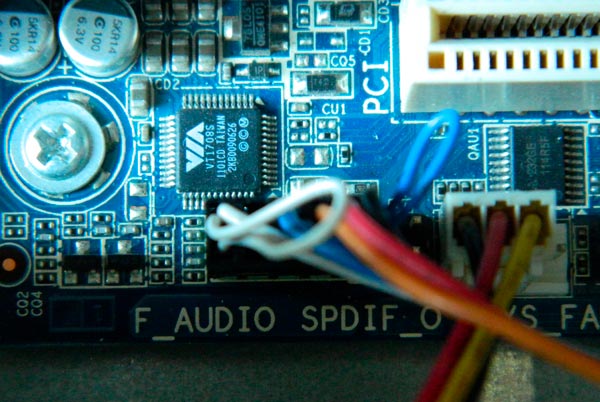
A little to the right are connectors for connecting the front USB ports. Agree, it’s not very convenient when they don’t work, and in order to quickly connect a memory card you have to crawl under the table to the system unit. There is a corresponding inscription on the wire that cannot be confused in any way. In this case, it is a blue wire.

The next step is to connect the wires labeled HDD LED, Power SW, Reset SW and Speaker. Each of them has its own function, so it is impossible to exclude any of them. The first wire on the list is responsible for indicating the operation of the hard drive. A very important parameter, since all computer data is stored on it.

Next, next to it in the bottom row, the wire responsible for restarting the computer is connected. If it is not connected, the small button on the front panel of the system unit will not work and there will be no way to restart the computer in emergency mode.

Above it are the contacts responsible for starting the computer. If you close these two contacts with a regular screwdriver, the computer will turn on itself.

In the upper right part you need to connect the Speaker wire, which is responsible for all the signals that the computer emits at startup. By these sounds you can determine all the problems associated with the computer hardware. This is what the motherboard panel should look like with all the wires connected.

If everything is done correctly, then you can now safely use the elements that are located on the front of the system unit, turn on and restart the computer.
Few novice users decide to implement the process of assembling a computer system with their own hands. Nevertheless, this “purchase option” is considered to be the most profitable. Since the user himself decides what exactly the hardware configuration of his computing device should be. At the same time, the correct connection of the front panel to the motherboard is a very important point in the overall assembly process. Some intricacy of the mentioned operation requires knowledge and precise actions from the practitioner. However, more details about everything in the following article.
Instead of introduction: claws, plugs and plug connectors
After you have installed the central processor, positioned and secured the main element of its cooling - the cooler, inserted RAM strips into special slots and equipped the motherboard with a hard drive (in general, installed important PC components), the moment comes when you need to connect the front panels to the motherboard. However, for many novice users, the last operation sometimes becomes simply impossible. After all, the system unit often has a bunch of incomprehensible wires. In some cases, their “quantity” is striking in its diversity and mystery of purpose. Since the case manufacturer does not always adhere to generally accepted standards, changing the cable markings and their location. However, everything can be easily resolved if the user carefully studies the technical documentation for the purchased device and strictly follows the installation instructions described below.
Trigger elements and indications
So, before carrying out the direct process - connecting the front panel to the motherboard, you need to conduct a visual inspection of the main system part for an accumulation of plug-type contacts. In other words, you need to find out where the connector pad is located through which the computer starts. After all, most motherboards, in addition to the main startup/shutdown and reboot unit, have in their, so to speak, configuration arsenal a number of additional connectors, which will also be discussed within the framework of this article.

- When connecting the front panel to an Asus motherboard (the brand is indicated as an example), locate the connector pad labeled “Front panel.”
- Focus on the color coding of the contact pads and their designation.
- The two-pin “Power SW” wire must fit into the corresponding socket, as well as the other control cables: “Reset SW”, “HDD LED” and “Power LED”. By the way, when connecting the last group of contacts, it is necessary to observe the polarity (there are “+” and “-” signs on the board).
- The “Speaker” sound sensor is also connected according to the principle described above.
Important digression
If for any reason you reverse the polarity or incorrectly position the mentioned controls, the computer may not start at all, or there will be no light indication of the operating equipment.

Therefore, be extremely careful when connecting the front panel to the motherboard. However, don't worry too much if something goes wrong. You can always correct a connection error by moving the incorrectly connected wires to a position that corresponds to the working diagram.
Additional interface connectors
Modern system units, in addition to the “Power” and “Reset” buttons located on the front of the case, are often equipped with additional Audio and USB ports. In some cases, there may be a card reader (a device for reading/writing memory cards) and even an IEEE 1394 connector, through which various peripheral devices can be connected. In any case, to improve the comfort of working on a PC, additional interface connectors must be activated. That is, first of all, they need to be physically connected to the motherboard and, if necessary, make some changes to the BIOS firmware parameters. However, let's not get ahead of ourselves...
Front Panel USB Connection

The motherboard (when you purchase it directly from the store) is always accompanied by a technical data sheet, which indicates the location of a specific connector and its purpose. At the same time, in the documentation the user can always find a graphically displayed connection diagram for the required device.
- Locate the pin connector labeled USB on the system board. You'll likely find several of them. By the way, in multifunctional modifications of computers there can be up to ten such ports.
- Connect the connector coming from the front panel to the nine-pin socket.
- Make sure that the joints of the plastic parts fit tightly together.
In the case when the USB connector connected to the board does not have an integral structure, for example, it has a limit switch branched into four pins, use the following instructions.
Resolving a difficult situation: USB “pinout”

As a rule, each of the four pins has its own designation in the form of an inscription:
- “VCC” is the wire that receives +5 Volt power.
- “Data -” or “D -” is negative data.
- “Data +” or abbreviated “D +” is the opposite of the previous point.
- "GND" - ground (mass).
When the user connects the front panel connectors to the motherboard, he must remember that if the “pinout” is incorrectly used, there is a risk of damaging any system component. As you understand, haste and rash actions can cost you dearly. Therefore, connect each wire to a strictly defined location on the mother connector.
- "VCC" is the first one.
- Then, “Data -”.
- The third pin is “Data +”.
- The last one is "GND".
By the way, after the “ground” there remains an unoccupied pin of the first port; the lower row of connectors is connected according to the instructions described above. However, there will no longer be an “extra” pin after the mass. As you can see, everything is simple!

Agree, it’s convenient when there is a microphone input jack and an Audio output for headphones on the front side of the PC case. However, despite the simplicity of immediately connecting an additional audio panel to the motherboard of your PC, the user is often faced with an incomprehensible effect - the connectors do not work properly or do not function at all. To avoid such an unpleasant situation or to understand the true reasons for “digital silence”, you need to do the following:
- Make sure the front audio panel matches your motherboard's audio standard and is connected to the appropriate "F-AUDIO" connector.
For example, if your motherboard supports “HD Audio”, then most likely this mode is activated by default, which means that the external “AC’97” module will not work. If the stipulated condition can be corrected by reconfiguring some software components, then if we consider the above situation in the context of the opposite, it will be necessary to completely replace the external audio module. The fact is that the “HD Audio” standard uses different codecs than “AC’97” and is incompatible in use with the latter due to some technical differences.
How to enable front panel connection in BIOS?
Just enter the BIOS firmware and find the corresponding audio device settings section. As a rule, you can make the necessary changes by using the “Advanced” tab, and by going to the “Front panel select” parameter change checkbox, set the desired working value. It is worth noting that a particular computer manufacturer equips its devices with the original version of the basic system. Therefore, some names of the BSVV control interface items may be designated differently.
Changes to settings in Sound Manager
Sometimes this happens: despite the front panel being correctly (physically) connected to the Gigabyte motherboard, the audio devices connected to the front connectors do not work.

The sound "snag" is resolved as follows:
- Go to Realtek HD Manager and enable the Disable Front Panel Jack Detection option.
- It may be that in the main “Connector Parameters” settings you need to enable the “item” that corresponds to the sound standard of the external audio module.
Finally
So, if you, dear reader, have a diagram for connecting the front panel to the motherboard (and this is not difficult to find out by looking at the technical documentation of your device), then a positive result is guaranteed. Remember that an incorrectly used connector can cause total breakdown of your computer. That's it - rational decisions and full-fledged achievements for you!
— the front side of the computer case has PC controls and switching controls. In particular, there are startup keys, PC reboot keys, and a disk drive key. LED indicators for visual monitoring of the hard drive status and PC power-on indicator.
Also, depending on the design of the system unit, there are built-in jacks for connecting headphones, additional speakers and USB ports. The steps to connect the front panel to the motherboard are not difficult in themselves. This is provided that you have skills in assembling a system unit.
Important information
Therefore, a thorough knowledge of what functions this or that element in the system unit performs is an excellent start in assembling the device yourself. Of course, complete with a factory-made system unit, as a rule, there are instructions that will help you understand everything. By the way, even if the document is in English, and you don’t know it, it will still help you intuitively understand what to connect where.
Recording the purpose of computer components in your memory is not difficult. Because there is a marking next to any element installed on the motherboard. It should be borne in mind that the tips given in this article are advisory in nature. Therefore, the location of the elements on your motherboard may be slightly different.
Step 1: Connecting buttons and LED indicators
A process like connecting the front panel to the motherboard is one of the important parts of installation. In this case, the first step is to connect all the wires coming from the front wall to the appropriate connectors.
Any motherboard has a special section used for switching signal wires coming from the power and indication buttons. On this site there are information signs like: “Front panel” or simply “PANEL”. This area is located along the edge of the board, opposite the front wall of the case.
Warning: If your actions were incorrect, it turned out that the front panel wires were connected with the wrong polarity. Or installed in other slots not intended for them. Then it is quite likely that the computer will refuse to start at all or the display will not work.
Based on this, try to be careful when performing connecting the front panel to the motherboard. Although, there is no need to worry too much if something is mixed up. Problems such as incorrect connection of wires are always easily corrected, and nothing terrible will happen. You just need to take a closer look at the markings again and reinstall the connectors correctly.
The connectors used to connect to the front panel are shown here:
- Red wire – designed to connect the on/off button;
- Yellow wire – connects to the computer reset button;
- The blue cable is responsible for one of the system status indicators, which usually lights up when the PC reboots (some models of cases do not have this);
- The green cable is designed to connect the motherboard to the computer's power indicator.
- The white cable is needed to connect the power.
The connection points of the connectors are usually marked with a color mark in accordance with their purpose or another mark that is printed on the connector itself. If for some reason you do not have these designations, then there is nothing to worry about either. Just make the connection, as people say, using the “poke” method, even if you make a mistake, it’s never too late to reinstall the contact connectors. 
To check that the wires are connected correctly, turn on the computer and press the start button located on the case. If the wires are connected correctly, the computer will turn on normally and the indicators will light up. If the PC does not turn on or there is no LED indication, then disconnect the PC from the network. Next, you need to try to reinstall the contact wires, and swap them in places.
Step 2: Connect the remaining components
At this step, connect the USB ports and the computer Speaker. Some configurations of system units are not equipped with these elements on the front panel. Therefore, if your case does not have USB ports on the front, then skip this step.
The steps to connect the USB port wire are as follows. You need to take a wire marked “USB” and connect it to the connector on the “motherboard”, which has a blue wire. If your motherboard has USB 3.0 installed, then you will have to resort to the instructions. Since in this option you will need to connect the wire to only one pin connector. Otherwise, the computer will not perform its intended functions via the USB ports.
The audio cable is connected in the same way; its connector is almost similar to the USB connector. However, it is made with a different color designation and its name could be AC90 or something similar. Its location is usually located near the USB connection point; there is only one on the motherboard.
Front Panel Connections
Assembling a computer is not only about connecting large components of the system unit, such as a hard drive, video card, processor or power supply. During assembly, it is necessary to connect the case itself to the “insides” of the computer. Several important elements are displayed on the body. At a minimum, these are power and reset buttons, as well as a hard drive activity indicator. If we are talking about more advanced cases, then some connectors can be placed on the front panel, in particular, USB and inputs for headphones or a microphone. In this article, we will tell you how to connect the front panel of your computer so that all elements on it work correctly.
First, it should be noted that there should be several wires coming from the computer case. In common parlance they are called “pins” from the English word Pin, which means “Pin” or “Pin”. Computer case wires are tiny, and they are connectors into which plugs located on the computer's motherboard are inserted. 
Before you begin directly connecting the front panel of the computer to the motherboard, you need to decide which wire is responsible for which task. To do this, just look at the inscriptions on the connectors. The following symbols can be found on them:

The standard names are listed above. The connector responsible for USB can be labeled - USB 2.0 and USB 3.0. If they are both signed as USB, then it is easy to identify the connector from the faster data transfer protocol - it has more inputs.
Front panel of the computer: connecting the power and display buttons
There is nothing complicated about connecting the front buttons and indicators to the computer motherboard. To do this, you need:

Please note that the connectors and plugs are, in most cases, protected against incorrect connection. That is, it simply won’t be possible to connect them to each other incorrectly without breaking the contacts.
Front panel of the computer: connecting USB and 3.5 mm connectors
When connecting connectors on the front panel of the computer, you must follow the same rules: find the connection location in the instructions and then connect the plug to the connector. Please note that there may not always be space on the motherboard to connect the front USB 3.0 connector. If there is nowhere to turn it on, you will have to leave it unconnected.
It is worth noting that the connectors for connecting audio outputs can be included in a common block with a front display and power buttons, or they can be located separately on the motherboard. USB connectors are always located separately, and their connection location on the motherboard is labeled F_USB, JUSB or USB 3.0. The first two options are typical for the USB 2.0 connector, which is connected via 10 pins, while the 3.0 connector requires 20 pins. 
It is quite difficult to make a mistake in the process of connecting buttons, connectors and indications from the front panel. The main thing when performing this work is accuracy, since the connectors for the front connectors on the motherboard are very thin, and excess force can damage them.
