A simple power supply. Making a transceiver power supply Power supply 13.8 v
The task was to make a power supply for the KEWOOD TS-850 HF transceiver instead of a failed switching power supply, which broke down during a heavy thunderstorm in the summer, the antenna was not turned off at that time and when turned on in the apartment panel, the circuit breaker was knocked out. After reading a discussion of home-made power supplies on various forums, we came to the conclusion that it is necessary to make a transformer home-made power supply, although it will turn out to be not very light in weight, but it can be repaired at home anyway, especially since there are many different pieces of iron in stock and it's a sin not to use them.
- The first question is: for what maximum current should it be made? According to the passport data, the maximum value of the current consumed by the TS-850 is 22 Amps, in reality it consumes less current. The output voltage for the transceiver is standard - 13.8 Volts.
- We begin to select the appropriate transformer, its power should be approximately 13.8 V * 22 A = 303.6 watts. If we carefully analyze the power characteristics, then from the transformers of the TN and TPP series they have a maximum power of 200 W, which means that we need to select two transformers and the total rated power will be 400 W. At first glance, the TPP-317, TPP-318, TPP-320 transformers are suitable (we look primarily in terms of power and current) and if the windings are connected in parallel and in series, then the TPP-320 transformer in the amount of 2- x pieces.
To increase the reliability of the power supply at maximum current, it was decided to increase the number of output transistors, in addition to reducing the current passing through the output transistors (the current is divided by the number of transistors), respectively, and the heat dissipation on each key is reduced, which is very important.

The design of the radiator with four transistors installed on it, in this case transistors in the TO-3 package were used, in the original version it was planned to install KT819G, but as a result of testing different power supply circuits, the stock of domestic transistors ended and I had to buy imported ones - 2N3055, which are cheap , although more powerful semiconductors are available today. The R. RAVETTI (I1RRT) power supply circuit, during testing, it showed, in my opinion, the best characteristics with the simplicity of the circuit.
The photo shows transistors mounted on a heatsink and wire-wound equalization resistors with a value of approximately 0.1 ohms. It is planned to install two such strips with a radiator, which will eventually amount to 8 transistors connected in parallel. The circuit is assembled by surface mounting, the case is selected in suitable dimensions from the device 30.5x13.0x20.0 cm.


The Kenwood TS-850 HF transceiver is connected to a self-made transformer power supply; in receive mode, the transceiver consumes about 2 amperes, which can be seen from the dial ammeter.


In the picture, the current consumption of the Kenwood TS-850 HF transceiver from the power supply when transmitting in CW mode is 15 amperes (under load, the supply voltage is 13.6 volts - see the voltmeter scale reading to the left of the ammeter), in the photo on the right is the TPP-320 transformer.
This power supply can be used for FT-840, FT-850, FT-950, IC-718, IC 746pro, IC -756pro, TS-570, TS 590S and other similar transceivers.
Somehow recently, on the Internet, I came across one circuit of a very simple power supply with the ability to adjust the voltage. It was possible to regulate the voltage from 1 Volt to 36 Volts, depending on the output voltage on the secondary winding of the transformer.
Take a close look at the LM317T in the circuit itself! The third leg (3) of the microcircuit clings to the capacitor C1, that is, the third leg is the INPUT, and the second leg (2) clings to the capacitor C2 and a 200 Ohm resistor and is the OUTPUT.
With the help of a transformer from a mains voltage of 220 volts, we get 25 volts, no more. Less is possible, more is not. Then we straighten the whole thing with a diode bridge and smooth out the ripples with the help of capacitor C1. All this is described in detail in the article how to get a constant voltage from an alternating voltage. And here is our most important trump card in the power supply - a highly stable voltage regulator chip LM317T. At the time of this writing, the price of this microcircuit was around 14 rubles. Even cheaper than a loaf of white bread.
Description of the microcircuit
LM317T is a voltage regulator. If the transformer produces up to 27-28 volts on the secondary winding, then we can easily regulate the voltage from 1.2 to 37 volts, but I would not raise the bar for more than 25 volts at the output of the transformer.
The microcircuit can be executed in the TO-220 package:

or in D2 Pack

It can pass a maximum current of 1.5 amps through itself, which is enough to power your electronic gadgets without a voltage drop. That is, we can give out a voltage of 36 Volts at a load current of up to 1.5 Amperes, and at the same time, our microcircuit will still give out 36 Volts as well - this, of course, is ideal. In reality, fractions of a volt will drop, which is not very critical. With a large current in the load, it is more expedient to put this microcircuit on a radiator.
In order to assemble the circuit, we will also need a 6.8 Kilo-ohm variable resistor, maybe even 10 Ki-ohm, as well as a 200 Ohm fixed resistor, preferably from 1 watt. Well, at the output we put a capacitor of 100 microfarads. Absolutely simple scheme!
Assembly in hardware
Previously, I had a very bad power supply still on transistors. I thought why not remake it? Here is the result ;-)
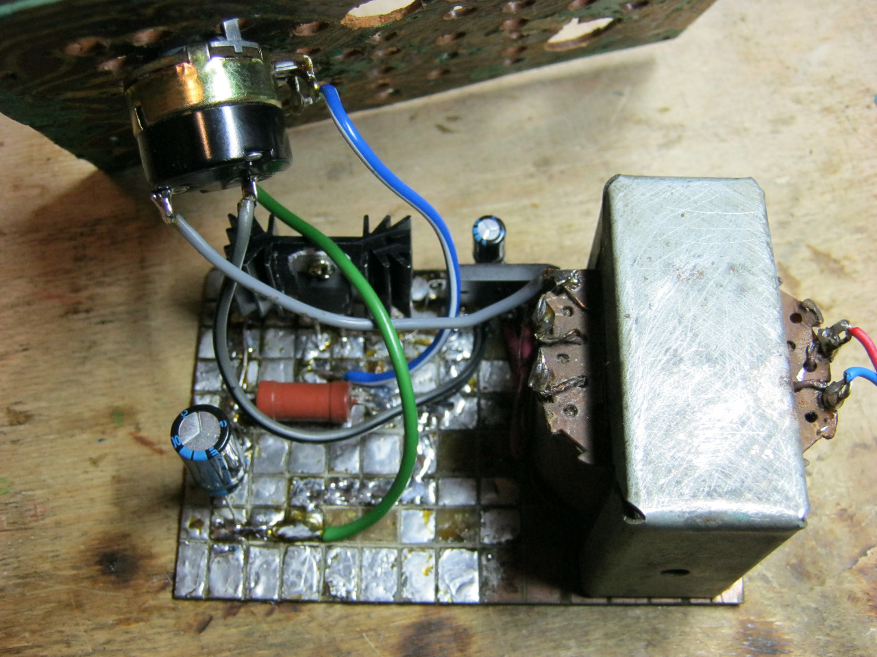
Here we see the GBU606 imported diode bridge. It is designed for current up to 6 amperes, which is more than enough for our power supply, since it will deliver a maximum of 1.5 amperes to the load. I put the LM-ku on the radiator using KPT-8 paste to improve heat transfer. Well, everything else, I think, is familiar to you.
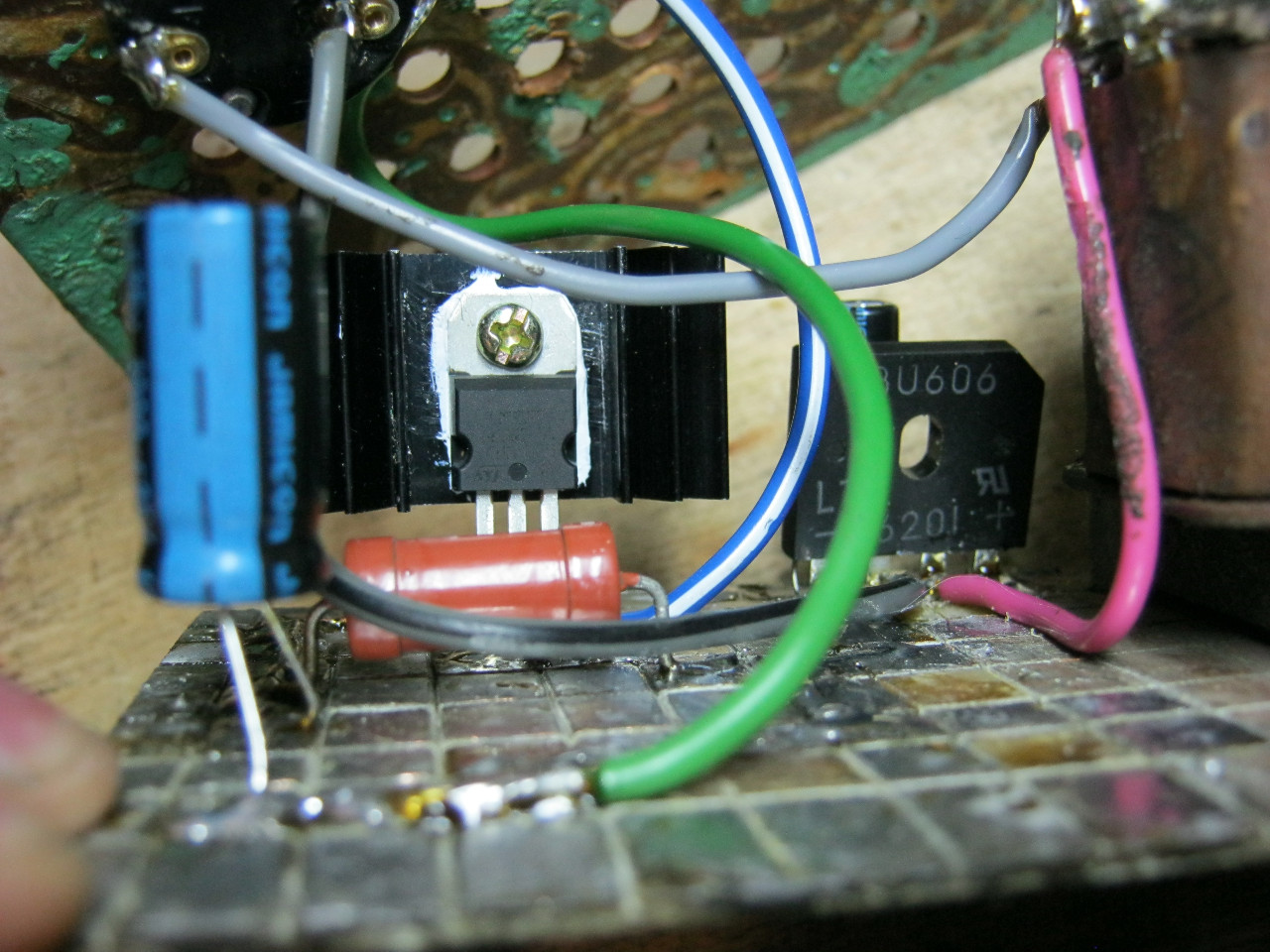
And here is the antediluvian transformer, which gives me a voltage of 12 volts on the secondary winding.

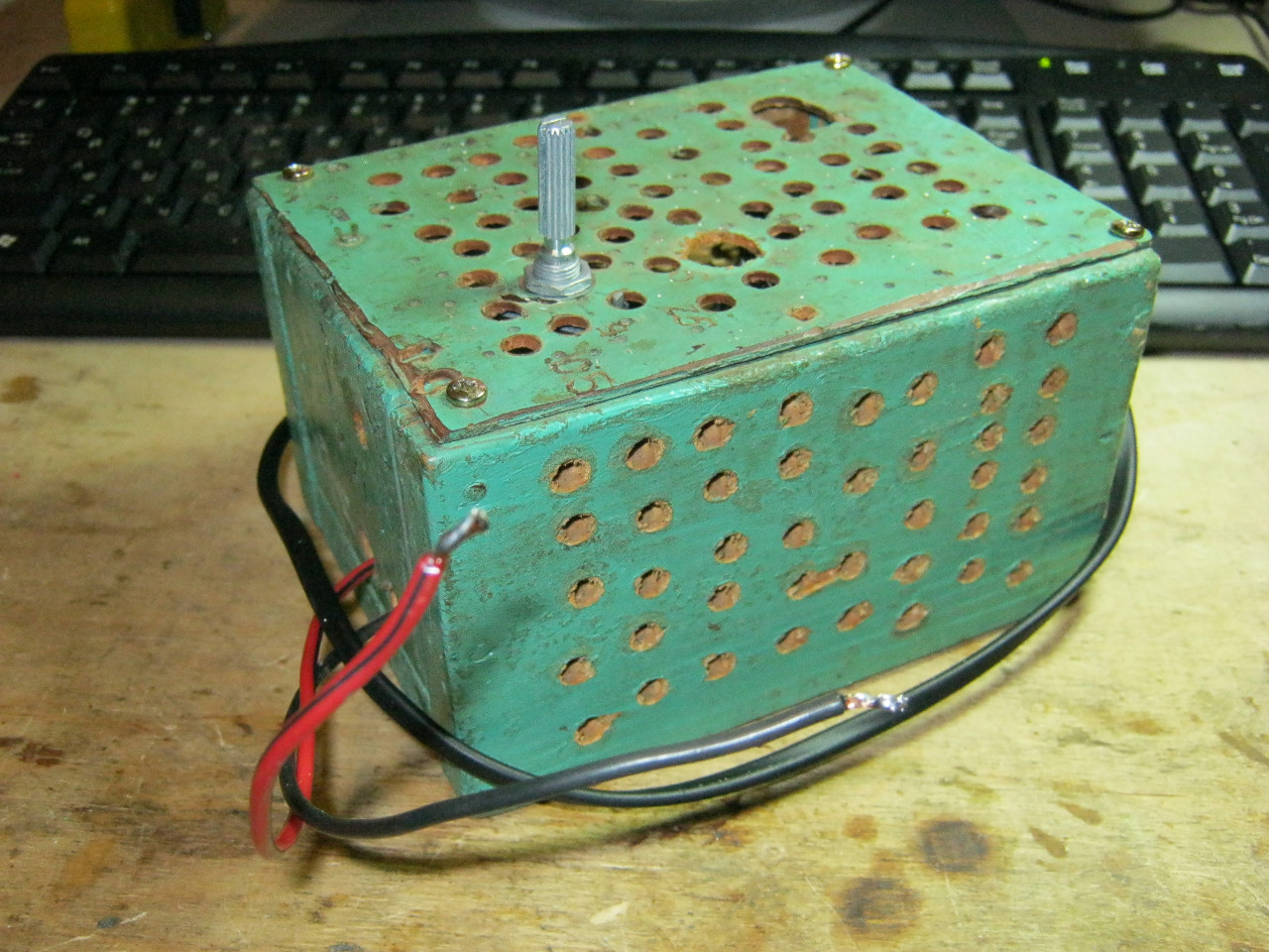
We carefully pack all this into the case and remove the wires.

So what do you think? ;-)
The minimum voltage I got was 1.25 Volts, and the maximum voltage was 15 Volts.


I put any voltage, in this case the most common 12 Volts and 5 Volts
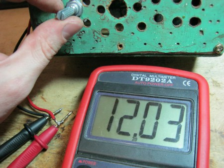

Everything works with a bang!
This power supply is very convenient for adjusting the speed of a mini drill, which is used for drilling boards.

Analogues on Aliexpress
By the way, on Ali you can immediately find a ready-made set of this block without a transformer.

Too lazy to collect? You can take a ready-made 5 Ampere for less than $ 2:

You can view by this link.
If 5 Amperes is not enough, then you can look at 8 Amperes. It will be enough even for the most seasoned electronics engineer:

Power supply 13.8V 50 A
It's no secret that powerful field-effect transistors (they are also mosfet) can work even with a very small voltage drop across them. It seemed very tempting to apply this property of theirs in a high-current voltage regulator. I have developed a power supply design for low-voltage equipment with a maximum current of up to 50A.
Description.
A feature of this design is the function of disconnecting the load in the event of a short circuit or overcurrent. Agree - a very valuable quality for a power supply ...
Since the starting current of such a device can be very large, then no, even a very powerful mechanical power switch, will last long. I had to introduce a soft start circuit for the power supply and what is called the "duty room" in computer PSUs. A small power supply on the Tr2 transformer is constantly connected to the network, its task is to control the on / off of the powerful part of the unit and generate an increased voltage to power the reference stabilizer. When connected to the network, a constant voltage of about 24 volts appears at the output of the rectifier. The presence of the standby voltage is indicated by the yellow LED2 (Ready). When the S1 (Power ON) button is pressed, a constant voltage is supplied through its contacts to the gate of the transistor T4, it instantly opens, the relay P2 is activated, which, with its contacts, connects the primary winding of the transformer Tr1 to the network. To prevent burning of relay contacts P2 and failure of rectifier diodes, a "soft start" device was used - initially, mains voltage is supplied through a series-connected resistor R1, which limits the starting current and is shunted by relay contacts P1 only after the voltage across capacitor C7 reaches the trip level relay. (12 volts approximately). Further, the rectified voltage is supplied to the stabilizer itself. Its circuit is borrowed from the datasheet on the TL431 chip, which is the source of the reference voltage for the applied stabilizer. Now - one subtlety that distinguishes this circuit from the standard one recommended by the manufacturer - to increase the efficiency of the stabilizer, that is, to reduce the voltage drop across the regulating element, a separate power supply for the reference source was used from the "duty room". At the same time, the difference between the input and output voltages of the stabilizer can be 2-3 volts (maybe even less, but it’s better not to risk it), while the ripple level remains very, very small. Now let's go back to the duty room, where we pressed the "Power ON" button, the transistor T4 is open, which leads to the opening of the transistor T5, through which power is supplied to the reference voltage source, the regulating transistors T1, T2 also open, the stabilizer enters the operating mode, then there is a stable voltage of 13.8 volts set at the output ... LED1 (red) lights up, and part of the output voltage through the trimmer resistor and diode D7 goes to the gate T4 ... That's it, now the button S1 can be released - the transistor T4 will be held open due to the output voltage of the stabilizer. It may seem like a long process, but no - the entire startup procedure takes about one second of time. By the way, this is a very good protection against accidental activation, this is how most consumer electronic devices work. To turn off the power supply, just briefly press the S2 (Power OFF) button. At the same time, the transistor T4 will close, the relay P2 will disconnect the power part of the PSU from the network, the transistor T5 will close at the same time, which will lead to a loss of power to the reference voltage source and, accordingly, to the shutdown of the stabilizer. When the S2 button is released, the device will remain in standby mode, since the voltage at the T4 gate will be absent ... A similar procedure occurs with a short circuit (even a very short one) at the PSU output or when the current protection is triggered. The result is always the same - the device goes into standby mode. To facilitate the thermal regime and reduce the area of the radiators, forced air cooling of the block was used. The speed of rotation of the fan motor and, accordingly, the efficiency of the blower are regulated by a simple circuit on the T6 transistor, depending on the temperature of the radiator.
Details, design and customization.
The parameters are determined primarily by the applied transformers and the design of the entire device. I used three TPP318 transformers in parallel as a power transformer and a transformer from_what_I don't_know with a power of 20 watts for the "duty room". Three TPP318 provided a rectified and filtered voltage (before the stabilizer) of 20 volts at idle and 16 volts at a current of 50A. A simple calculation shows that even at the maximum current, the power dissipated by the control transistors does not exceed 100 watts, which is less than the maximum power dissipation even for one transistor ... Powerful control transistors can be used of the IRF150 or IRF250 types, as well as others in metal TO cases -3 and with a maximum current of more than 30A. The duty transformer must provide 24 volts of rectified voltage with a current of at least 0.5A.
To improve and speed up the response of the protection, the output voltage control wire (to LED1) must be connected directly from the positive terminals of the PSU.
Relay P1 - REN34 and R-2 - REN33. The operation voltage R-1 should be 12v, and R-2 - 24v. You can use other relays with appropriate operating voltages and sufficiently powerful contacts. Rectifier bridge in the duty room - any for a current of at least 1A, diodes in a powerful rectifier - KD2999A. Diodes D5 and D7 - any low-power ones, I used 1N4001. The mains filter is made on a ring made of ferrite 2000NN with a diameter of 40 mm, 12 turns of a double mains wire are wound on it. Filter capacitors and C8 are ceramic, for a voltage of at least 1KV. The remaining blocking capacitors - smd, electrolytes - for an operating voltage of at least 25 volts. R3 and R4 are pieces of thick wire made of high-resistance alloy 50mm long.
A properly assembled PSU does not need any special adjustment. It is only necessary to set the exact output voltage with R14, and with R16 the minimum voltage at the T4 gate is set, which keeps it open. This speeds up the protection. For blowing, a computer fan with an operating voltage of 12 volts was used. With the help of a tuning resistor, a small rotation speed is set in its "cold" state, with an increase in temperature, the resistance of the thermistor decreases, which leads to an increase in the voltage at the base of T6 and to an increase in the blowing speed. Buttons S1 and S2 - any, without fixing, their contacts can be very underpowered.
When manufacturing a PSU, all known recommendations for such devices should be taken into account - the installation should be done with as thick and short wires as possible, the output terminals should "hold" a current of tens of amperes. Measuring device - any pointer with the appropriate shunt.
The proposed power supply (Fig. 1) is designed to work with a powerful low-voltage load, for example, with VHF FM radio stations with an output power of about 50 W ("Alinco DR-130"). Its advantages are low voltage drop across the rectifier diodes and the regulating transistor and the presence of short circuit protection.
Mains voltage through the closed contacts of the switch SA1. fuse FU1 and mains filter C5-L1-L2-C6 is supplied to the winding I of the power transformer T1. From the secondary winding II T1, which has a tap from the middle, the positive voltage half-waves through the rectifier diodes VD2 and VD3 are fed to the smoothing filter capacitor C9.
A linear stabilizer with a regulating element on a field-effect transistor (FET) VT2 is connected to the filter. To control this transistor, a voltage of 2.5 ... .3 V is required, so there is no need for a separate rectifier to power the control circuits of the FET, such as in. To increase the stabilization coefficient in the stabilizer, an "adjustable zener diode" is used - a DA1 TL431 microcircuit (domestic analogue - KR142EN19). Transistor VT1 - matching, zener diode VD1 stabilizes the voltage in its base circuit. The output voltage of the stabilizer can be calculated using the approximate formula
The stabilizer works as follows. Let's say that when the load is connected, the output voltage decreases. Then the voltage at the midpoint of the divider R5-R6 decreases, the DA1 chip (as a parallel stabilizer) consumes less current, and the voltage drop decreases on its load (resistor R2). This resistor is in the emitter circuit of the transistor VT2 and, since the voltage at its base is stabilized by the zener diode VD1. the transistor opens more strongly, providing an increase in the voltage at the gate of the regulating transistor VT2. The latter opens more and compensates for the voltage drop at the output of the stabilizer. Thus, the stabilization of the output voltage is ensured. The output voltage is set by resistor R6. Zener diode VD6. connected between the source and gate VT2. serves to protect the FET from exceeding the permissible gate-source voltage and is an indispensable element in stabilizers with an input voltage of 15 V and above.
This power supply is a variant of the device described in. The same stabilizer with protection is used here, but the two-stage start-up of the PSU and the overvoltage protection circuit are excluded. A meter for the output voltage and load current was added to the power supply unit on the RA1 pointer device (the head of the M2001 microammeter with a total deviation current of 100 μA), an additional resistor R7, a shunt RS1, an interference suppression capacitor C12 and a switch SA2 ("Voltage / current"). Since the temperature regime of the PT in this PSU is light, a PT of the IRF2505 type was used in the TO-220 package, which has a higher thermal resistance than IRF2505S.
The TN-60 transformer is found in two modifications: powered only from a 220 V network and with a combination of primary windings that allow the transformer to be connected to a network with voltages of 110.127. 220 and 237 V. The connection of the windings T1 in Fig. 1 is shown for a voltage of 237 V. This is done in order to reduce the no-load current T1, reduce the stray field and heating of the transformer, and increase efficiency. In networks with low voltage (relative to 220 V), terminals 2 and 4 of the primary windings are connected to each other. Instead of the TN-60 transformer, TN-61 can be used.
To reduce the "drawdown" of the voltage under load, a rectifier circuit with a midpoint using Shot-ki diodes was used. the inclusion of the T1 windings is optimized in order to evenly distribute the load on them. The installation of the power supply circuits of the power supply unit is made with a wire with a core cross section of at least 1 mm2. The Schottky diodes are installed without gaskets on a small common radiator from an old computer monitor (aluminum plate), which, using the available pins, is soldered into the panel, on which a set of C9 capacitors (4 pieces of 10,000 uFx25 V) is placed. The RS1 shunt for measuring the load current is a "positive" wire connecting the bus on the printed circuit board from the C9 pins to the load connection terminal.
Structurally, the PSU is made very simply (Fig. 2). Its rear wall is a radiator, the front wall (panel) is a piece of duralumin of the same length and width, 4 tAtA thick. The walls are fastened together with 4 studs 07 mm made of steel. They have end holes with M4 thread. A shelf made of 2 mm thick duralumin according to the size of the transformer is screwed to the lower pins (4 M4 screws). A plate of one-sided o-yulgated fiberglass 1.5 mm thick is attached in the same way. on which capacitors C9 and a radiator with diodes VD2, VD3 are mounted. On the front panel there are two pairs of output terminals (parallel), measuring head PA1. output voltage regulator R6, current/voltage switch SA2. fuse holder FU1 and power switch SA1. The case for the PSU (U-shaped bracket) can be bent from mild steel or assembled from separate panels. The radiator for the PT (123x123x20 mm) was used ready-made, from the power supply unit of the old Kama-R VHF radio station. The length of the fastening pins is 260 mm. but can be shortened up to 200 mm with tighter mounting. Plate dimensions: duralumin under T1 - 117.5x90x2 mm, fiberglass - 117.5x80x1.5 mm.

Line filter coils L1. L2 are wound with a flat two-wire power cord on a ferrite core (400НН.. .600НН) from the magnetic antenna of the radio receiver (before filling). Rod length - 160...180 mm, diameter - 8...10 mm. Capacitors of the K73-17 type are soldered to the coil terminals, designed for an operating voltage of at least 500 V. The assembled filter is wrapped in a non-hygroscopic material, for example, electrical cardboard, on top of which a solid tinplate screen is made. The seams of the screen are soldered, the leads pass through the insulating sleeves.
A stabilizer is good for everyone, but what happens if the load current exceeds the limit value for the regulating transistor, for example, due to a short circuit in the load? Obeying the described algorithm of work. VT2 will fully open, overheat, and quickly fail. For protection, you can apply an optocoupler circuit. In a slightly modified form, this protection is shown in Fig. 1.
The parametric stabilizer on the VD4 zener diode provides a reference voltage of -6.2 V, voltage surges and noise are blocked by the capacitor SU. The output voltage of the stabilizer is compared with the reference voltage through the LED chain of the optocoupler VU1-VD5-R10. The output voltage of the stabilizer is higher than the reference voltage, therefore, it biases the junction of the VD5 diode. locking him up. No current flows through the LED. When the output terminals of the stabilizer are shorted on the right output R10 according to the diagram, the negative voltage disappears, the reference one opens the diode VD5. The optocoupler LED lights up and the phototriac of the optocoupler fires. which closes the gate and source VT2. The control transistor closes, i.e. the output current of the stabilizer is limited. To bring it into operating mode after the protection is triggered, the PSU is turned off using SA1. remove the short circuit and turn it on again. In this case, the protection circuit returns to standby mode.
The use of such stabilizers with a low voltage drop across the FET makes it unnecessary to protect the powered equipment from overvoltage resulting from the breakdown of the control transistor. In this case, the output voltage increases by only 0.5 ... 1 V, which is usually included in the tolerance standards for most equipment.

Most of the PSU elements (circled in Fig. 1 by a dotted line) are placed on a printed circuit board 52x55 mm in size. the drawing of which is shown in Fig. 3, and the location of the parts on the board - in Fig. 4. The board is made of double-sided foil fiberglass with a thickness of 1 ... 1.5 mm. The foil on the bottom side of the board is connected to the negative output bus of the stabilizer ("grounded" in Fig. 1) with a separate wire. Free conclusions of the VU1 optocoupler can not be soldered anywhere. Holes are marked on the board at the soldering points, but mounting can be carried out from above, from the side of the printed conductors, without drilling holes. In this case, the drawing of the board corresponds to Fig.4. A drawing of the board, on which the heat sink with diodes and filter capacitors are located, is shown in Fig. 5.
Before assembling the PSU, be sure to check the ratings of all parts and their serviceability. Connections
inside the PSU are made with thick wires of minimum length. In parallel with all oxide capacitors, ceramic capacitors with a capacity of 0.1 ... 0.22 μF are soldered directly to their terminals.
The current meter can be calibrated by connecting an adjustable load to the PSU output terminals in series with an ammeter for a current of 2 ... 5 A. Having set the current, for example, 2 A, by the ammeter, we select such a length of wire (shunt), twisting a loop from it so that the arrow deflects RA1 was 20 divisions (with a scale of 100).

We transfer SA2 to another position, connect a control voltmeter to the PSU output, by selecting the resistance R7 (instead of it, you can turn on a tuning resistor with a resistance of at least 220 kOhm), we achieve the coincidence of the readings of PA1 with the readings of the voltmeter.
When working with radio transmitting equipment, interference with stabilizer parts, input and output wires should be excluded. To do this, at the output terminals of the PSU, you should turn on a filter similar to a network one (Fig. 1), with the only difference that the coils must be wound on a ferrite ring or ferrite tube used in old monitors and foreign-made TVs, and contain only 2-3 a turn of insulated wire of large cross section, and capacitors can be taken with a lower operating voltage.
Literature
1. V. Nechaev. Powerful voltage regulator module on a field-effect transistor. - Radio. 2005. No. 2, p.30.
2. Stabilizer with very low voltage drop.
3. V. Besedin. We defend ourselves ... - Radiomir, 2008. No. 3. C.12-
4. Precision filament stabilizer. -klausmobile.narod.ru/appnoIes/an_11_fetreg_r.htm
V. BESEDIN, Tyumen.
Power supply 13.8V 25-30A for a modern HF transceiver
In recent years, more and more CIS radio amateurs use foreign-made equipment to work on the air. To power most of the most common models of ICOM, KENWOOD, YAESU transceivers, an external power supply is required that meets a number of important technical requirements. According to the operating instructions for transceivers, it should have an output voltage of 13.8 V at a load current of up to 25-30 A. The output voltage ripple range is not more than 100 mV. In no case should the power supply be a source of high-frequency interference. The stabilizer must have a reliable system of protection against short circuits and against the appearance of increased voltage at the output, which works even in an emergency, for example, in the event of a breakdown of the main regulatory element. The described design fully meets the specified requirements, in addition, it is simple and built on an accessible element base. The main technical characteristics are as follows:
- Output voltage, V 13.8
- Maximum load current, A 25 (30)
- Range of output voltage ripple, no more than mV 20
- Efficiency at current 25 (30) A, not less than, % 60
The power supply is built according to the traditional scheme with a power transformer operating at a mains frequency of 50 Hz. In the circuit of the primary winding of the transformer, an inrush current limiting unit is included. This is done because a filter capacitance of a very large value, 110,000 μF, is installed at the output of the rectifier bridge, which is an almost short-circuited circuit at the moment the mains voltage is applied. The charge current is limited by R1. After about 0.7 seconds, relay K1 is activated and closes the limiting resistor with its contacts, which does not affect the operation of the circuit in the future. The delay is determined by the time constant R4C3. An output voltage stabilizer is assembled on transistors VT10, VT9, VT3-VT8. During its development, the scheme was taken as a basis, which has a number of useful properties. First, the collector terminals of the power transistors are connected to a ground wire. Therefore, transistors can be mounted on a heatsink without insulating gaskets. Secondly, it implements a short circuit protection system with a falling characteristic, Fig. 2. Therefore, the short circuit current will be several times less than the maximum. Stabilization coefficient is more than 1000. The minimum voltage drop between the input and output at a current of 25 (30) A is 1.5V. The output voltage is determined by the Zener diode VD6, and will be approximately 0.6 V more than its stabilization voltage. The current protection threshold is determined by the resistor R16. With an increase in its value, the operating current decreases. The magnitude of the short circuit current depends on the ratio of resistors R5 and R17. The larger R5, the less short-circuit current. However, it is not worth striving to significantly increase the value of R5, since the initial start of the stabilizer is carried out through the same resistor, which can become unstable when the mains voltage is reduced. Capacitor C5 prevents the stabilizer from self-exciting at high frequencies. Equalizing resistors are included in the emitter circuit of the power transistors 0.2 ohms for the 25-amp version of the power supply, or 0.15 ohms for the 30-amp version. The voltage drop across one of them is used to measure the output current. An emergency protection unit is assembled on the VT11 transistor and the VS1 thyristor. It is designed to prevent high voltage from entering the output in the event of a breakdown of the regulating transistors. Its schema is taken from . The principle of operation is very simple. The voltage at the emitter VT11 is stabilized by the Zener diode VD7, and at the base it is proportional to the output. If a voltage of more than 16.5 V appears at the output, the transistor VT11 will open, and the current of its collector will open the thyristor VS1, which will bypass the output and cause the fuse F3 to blow. The response threshold is determined by the ratio of resistors R22 and R23. To power the fan M1, a separate stabilizer is used, made on the transistor VT1. This is done so that in case of a short circuit at the output or after the emergency protection system has been activated, the fan does not stop. An alarm circuit is assembled on transistor VT2. In the event of a short circuit at the output or after the fuse F3 blows, the voltage drop between the input and output of the stabilizer becomes more than 13 V, the current through the zener diode VD5 opens the transistor VT2 and the BF1 buzzer beeps.

A few words about the element base. Transformer T1 must have an overall power of at least 450 (540) W and produce an alternating voltage of 18V at a current of 25 (30) A on the secondary winding. The conclusions from the primary winding are made at points 210, 220, 230, 240 V and serve to optimize the efficiency of the unit depending on the voltage of the network at a particular place of operation. The limiting resistor R1 is wire-wound, with a power of 10 watts. The VD1 rectifier bridge must be designed for a current flow of at least 50 A, otherwise, when the emergency protection system is triggered, it will blow out before the F3 fuse. Capacitance C1 consists of five 22000 μF 35 V capacitors connected in parallel. On the resistance R16 at the maximum load current, a power of about 20 W is dissipated, it consists of 8-12 resistors C2-23-2W 150 ohms connected in parallel. The exact number is selected when setting up short circuit protection. To indicate the value of the output voltage PV1 and the load current PA1, measuring heads are used with a current of arrow deviation per the last division of the scale of 1 mA. Fan M1 must have an operating voltage of 12V. These are widely used for cooling processors in personal computers. Relay K1 Relpol RM85-2011-35-1012 has an operating voltage of the winding of 12V and a contact current of 16A at a voltage of 250V. It can be replaced by another with similar parameters. The selection of powerful transistors should be approached very carefully, since the parallel circuit has one unpleasant feature. If during operation, due to any reason, one of the transistors connected in parallel breaks through, this will lead to the immediate failure of all the others. Before installation, each of the transistors must be checked with a tester. Both transitions should ring in the forward direction, and in the opposite direction, the deviation of the ohmmeter needle set to the x10 Ω limit should not be noticeable to the eye. If this condition is not met, the transistor is of poor quality and can fail at any time. The exception is the VT9 transistor. It is composite and inside the case the emitter junctions are shunted by resistors, the first is 5K, the second is 150 Ohm. See fig. 2.

When dialing in the opposite direction, the ohmmeter will show their presence. Most transistors can be replaced by domestic counterparts, albeit with some deterioration in performance. Analogue of BD236-KT816, 2N3055-KT819BM (required in a metal case) or better than KT8101, VS547-KT503, VS557-KT502, TIP127-KT825. At first glance, it may seem that the use of six transistors as the main regulatory element is unnecessary, and two or three can be dispensed with. After all, the maximum allowable collector current 2N3055 is 15 amperes. A 6x15 \u003d 90 A! Why such a reserve? This is because the static current transfer coefficient of a transistor is highly dependent on the magnitude of the collector current. If at a current of 0.3-0.5 A its value is 30-70, then at 5-6 A it is already 15-35. And at 12-15 A, no more than 3-5. Which can lead to a significant increase in ripple at the output of the power supply at a load current close to the maximum, as well as a sharp increase in the thermal power dissipated by the VT9 transistor and resistance R16. Therefore, in this circuit, it is not recommended to remove a current of more than 5A from one 2N3055 transistor. The same applies to KT819GM, KT8101. The number of transistors can be reduced to 4 by using more powerful devices, such as 2N5885, 2N5886. But they are much more expensive and more scarce. The thyristor VS1, like the rectifier bridge, must be designed for a current flow of at least 50A.
In the design of the power supply, it is necessary to take into account several important points. Diode bridge VD1, transistors VT3-VT8, VT9 must be installed on a radiator with a total area sufficient to dissipate thermal power of 250W. In the author's design, it consists of two parts that serve as the side walls of the case, and have an effective area of 1800 cm each. The VT9 transistor is installed through an insulating heat-conducting gasket. Installation of high-current circuits must be carried out with a wire with a cross section of at least 5 mm. The points of the ground and the plus of the stabilizer must be points, not lines. Failure to comply with this rule can lead to an increase in output voltage ripple and even self-excitation of the stabilizer. One of the options that meet this requirement is shown in Fig.4.

Five capacitors forming capacitance C1 and capacitor C6 are located on the printed circuit board in a circle. The platform formed in the central part serves as a positive bus, and the sector connected to the minus of the capacitor C6 is negative. The lower terminal of the resistor R16, the emitter VT10, the lower terminal of the resistor R19 are connected to the central platform with separate wires. (R16 - with a wire with a cross section of at least 0.75 mm) The right output of R17 according to the diagram, the anode VD6, the collectors VT3-VT8 are connected to the minus C6, also each with a separate wire. Capacitor C5 is soldered directly to the terminals of the transistor VT9 or located in close proximity to it. Compliance with the point grounding rule for the elements of the fan supply voltage stabilizer, inrush current limiter, alarm device is not necessary and their design can be arbitrary. The emergency protection device is assembled on a separate board and is attached directly to the output terminals of the power supply unit on the inside of the case.
Before proceeding with the setup, you should pay attention to the fact that the described power supply is a fairly powerful electrical appliance, which requires caution and strict adherence to safety regulations when working with it. First of all, you should not rush to immediately turn on the assembled unit to the 220V network, first you need to check the performance of the main components of the circuit. To do this, set the slider of the variable resistor R6 to the right extreme position according to the diagram, and the resistor R20 to the top. Of the resistors that form R16, only one should be set to 150 ohms. The emergency protection device must be temporarily disabled by unsoldering it from the rest of the circuit. Next, apply a voltage of 25V to the capacitance C1 from a laboratory power supply with a short circuit protection current of 0.5-1 A. After about 0.7 seconds, relay K1 should work, the fan will turn on, and a voltage of 13.8 V will appear at the output. The value of the output voltage can be changed by selecting a zener diode VD6. Check the voltage on the fan motor, it should be approximately 12.2 V. After that, it is necessary to calibrate the voltage meter. Connect a reference voltmeter, preferably digital, to the output of the power supply, and by adjusting R20 set the pointer of the PV1 device to a division corresponding to the readings of the reference voltmeter. To configure the emergency protection device, it is necessary to apply a voltage of 10-12 V to it from a laboratory regulated power source through a 10-20 Ohm 2 W resistor. (At the same time, it must be disconnected from the rest of the circuit!) In parallel with the VS1 thyristor, turn on the voltmeter. Then gradually increase the voltage and detect the last reading of the voltmeter, after which its readings will drop sharply to a value of 0.7 V (the thyristor has opened). By selecting the value of R23, set the response threshold at 16.5 V (The maximum allowable supply voltage of the transceiver according to the operating instructions). After that, connect the emergency protection device to the rest of the circuit. Now you can turn on the power supply to the 220 V network. Next, you should configure the short circuit protection circuit. To do this, connect a powerful rheostat with a resistance of 10-15 ohms to the output of the power supply through an ammeter for a current of 25-30 A. Gradually reducing the resistance of the rheostat from the maximum value to zero, remove the load characteristic. It should have the form shown in Figure 2, but with a bend at a load current of 3-5 A. When the resistance of the rheostat is close to zero, an alarm should turn on. Next, one by one, solder the remaining resistors (150 ohms each) that make up the resistance R16, each time checking the value of the maximum current until its value is 26-27 A for the 25-amp version or 31-32A for the 30-amp one. After setting the short circuit protection, it is necessary to calibrate the output current measuring device. To do this, use a rheostat to set a load current of 15-20 A and adjust the resistor R6 to achieve the same readings of the PA1 pointer device and the reference ammeter. At this point, the power supply setup can be considered complete and you can proceed to thermal tests. To do this, it is necessary to fully assemble the device, use a rheostat to set the output current to 15-20A and leave it on for several hours. After that, make sure that nothing has failed in the unit, and the temperature of the elements does not exceed 60-70 C. Now you can connect the unit to the transceiver and conduct a final check in real working conditions. It should also not be forgotten that the power supply includes an automatic control system. It can be affected by high-frequency interference that occurs when the transceiver transmitter is operated with an antenna-feeder path that has a high SWR value or asymmetry current. Therefore, it would be useful to make at least the simplest protective choke by winding 6-10 turns of the cable connecting the power supply to the transceiver on a ferrite ring with a permeability of 600-3000 of the corresponding diameter.
