Systems of excitation of synchronous machines. Methods of excitation of synchronous machines Design of synchronous machines with electromagnetic excitation
1.1 Structures of synchronous machines(Theme 19)
A two-winding AC machine is called synchronous, one of the windings of which is connected to an electrical network with a constant frequency. f 1 , and the second is excited by direct current ( f 2 = 0). The rotor speed of the synchronous machine is constant and for given constant mains frequency f 1 and the number of pairs of poles p is equal to
Synchronous machines also include machines with one connected to the network with a constant frequency f 1 winding and speed determined by the formula (1.1), as well as two-winding machines, the windings of which are fed with alternating currents with constant frequencies f 1 and f 2. In the latter case, the rotor speed
and is also constant at constant frequencies f 1 and f 2. The last two types of machines are called special synchronous machines.
stator(fixed part) of a synchronous machine consists of a housing, a magnetic circuit (core) with a winding, end shields and other structural elements.
Stator magnetic circuit 1 (Fig. 1.1) are assembled in the form of a ring from plates of sheet or rolled electrical steel with a thickness of 0.5 (less often 0.35) mm. Steel plates are stamped in the form of solid rings for magnetic circuits with an outer diameter of up to 1 m or segments with an outer diameter of more than 1 m. Notches (cavities) are stamped on the inner arc of the plates, which form during the assembly of the magnetic circuit grooves 2 for winding. On the outer arc of the plates, recesses in the form of a trapezoid (“dovetail”), less often a parallelogram or a circle, are stamped, which are used to assemble the magnetic circuit, sometimes in the form of a rectangle for ring plates. After deburring, the plates are insulated with varnish to reduce eddy currents and power losses created by currents.
Stator magnetic circuit segments collect on wedges (ribs) installed at an equal distance along the inner circumference of the body. Wedges 11 (Fig. 1.2 is attached to the body with the help of squares 10 welded on one side to the wedges 11 , and the other - to the horizontal shelves 3 corps. 5

On the surfaces of the wedges facing the center of the machine, protrusions are made in the form of a “dovetail” or another shape corresponding to the shape of the recesses on the outer arc of the segments. When assembling the magnetic circuit, the segments 12 put on the recesses stamped on the outer arc on the protrusions of the wedges (Fig. 1.2. b), fixing the segments from displacement in the radial and tangential directions. The segments of adjacent layers of the blend are displaced in a circle, usually by half a segment (Fig. 1.2, b). The segments of the next (upper) layer of the blend overlap the joints of the lower layer, which increases the rigidity and reduces the magnetic resistance of the magnetic circuit.
In high power generators (more than 50–100 MW), to reduce additional power losses and local heating of the end zone due to end magnetic fields, pressure fingers and annular flanges are made of non-magnetic steels; 1–3 extreme packs of stator steel are made of smaller thickness stepped (Fig. 1.2), radial slots (slots) are made in the teeth of the extreme packs.

The magnetic circuits of low-power machines from solid annular steel plates with an outer diameter of up to 0.5 m are assembled on an inner mandrel, pressed and then fastened along the outer diameter with brackets welded to the ends of the core, or strips welded at the ends of the core to pressure washers or ring flanges. forms. The assembled core (together with the winding) is pressed into a steel or cast iron frame. Magnetic circuits from ring plates with an outer diameter of 0.5 to 1 m are assembled directly into a bored body or onto the edges of the body and pressed between two pressure washers or rings, which are fixed in the body with locking keys or welding.
In grooves 2 (Fig. 1.1) the stator magnetic circuit is laid with three-phase or single-phase coils ( m - phase) distributed stator winding. Coils are wound with insulated copper wire. The stator winding is performed with the same number of pole pairs R as well as the rotor winding. The stator magnetic circuit together with the winding is called the armature. The anchor is installed in the middle part of the hull. The armature winding is connected to the AC network.
Rotor consists of a shaft and a magnetic circuit (core) with an excitation winding. Excitation winding connected to DC voltage Uf(Fig. 1.1) through fixed on the shaft slip rings 6 and brushes 7 brush apparatus fixed on the stator. under tension Uf a direct excitation current occurs in the field winding I f . Current I f forms a magnetic flux of excitation Ф f , most of the lines of magnetic induction B f which crosses the gap and closes along the magnetic circuits of the stator and rotor (Fig. 1.1).
A rotor with an excitation winding is called an inductor. Sometimes, in inverted machines, the stator serves as an inductor; the alternating current winding in such machines is placed on the rotor.
According to the design of the rotor There are two types of synchronous machines: salient pole(Fig. 1.1, a) and implicit pole(Fig. 1.1, b).
Machines with number of pole pairs p³ 2 is usually made with pronounced poles and is called explicit pole. Field coils 4 (Fig. 1.1, a) are electrically connected to each other in series so as to obtain an alternation of the polarity of the poles around the circumference of the machine: after the indicated letter N the north pole of the rotor is marked with the letter S south pole, beyond the south pole S north again N etc.
3 pole core(Fig. 1.1, a) are usually recruited from steel plates. For machines with a power of 100 kW or less, the pole plates are stamped from electrical steel with a thickness of 0.5–1 mm, at high powers - from low-carbon structural steel grade St.3 with a thickness of 1–1.4 mm (less often 2 mm).
The outline of the pole piece (the wider part of the pole) is made so that the gap between the stator core and the pole piece on the pole axis δ is 1.5–2.5 times less than the gap δm near the edges of the pole piece (Fig. 2.10). As a result, the induction distribution B δ f magnetic flux F f excitation winding in the gap approaches sinusoidal.
Notches are stamped in the pole pieces of the rotor plates, which form round semi-closed grooves when assembling the pole core. Cylindrical rods 14 (Fig. 1.3) made of metal with low electrical resistance. From the ends of the pole, the rods are connected short circuit segments 15 from a copper bar of rectangular section bent on an edge. The soldering of the joints of the rods with the segments is carried out with hard solders. The short-circuiting segments of adjacent poles are connected by conductive jumpers, as a result, a short-circuited winding, similar to the winding of a squirrel-cage rotor of an induction motor.
 In generators this winding is called damper or sedative and the rods are made of copper. It serves to reduce rotor oscillations during transients. in engines rods are made of brass the winding is called launcher. It serves for asynchronous start. Sometimes the poles of synchronous motors are made massive. The ends of the tips of adjacent poles are connected by conductive jumpers. In this case, massive poles play the role of a starting winding.
Steel Pole Sheets 1 tightened with steel pressure cheeks 9 and tie rods 10 (Fig. 1.3). Shell insulation 7 superimposed directly on the core of the pole in the form of several layers of fiberglass impregnated with thermosetting varnish. In high-power machines, body insulation is made in the form of solid boxes of pressed fiberglass on thermosetting binders.
A coil is installed on the insulated core of the pole. 2 excitation windings (Fig. 1.3). Sometimes, to fix the coil on the pole or create cooling channels, the coil is unfastened with insulating gaskets. 8 . From contact with the core or sleeve of the rotor and the pole piece of the excitation coil, the excitation windings are isolated with getinax or fiberglass washers 5 .
In machines of relatively low power (up to 100 kW), multilayer coils are used from insulated copper wire of round or rectangular cross section. For machines of medium and high power (over 100 kW), the coils are wound with a bare copper bus of a rectangular or special profile on an edge in one row along the height of the pole (Fig. 1.3), which improves heat removal from the side uninsulated surfaces of the coils. Neighboring turns 3 insulated with gaskets 4 made of fiberglass impregnated with epoxy or other thermosetting varnish. To give solidity, the coils are pressed and baked under pressure.
The poles are attached to the rim or hub of the rotor. Most often, the rim is assembled cross-cut from steel plates (segments) with a thickness of 2–100 mm, pulled together with studs. To stacked (laminated) rim 16 poles are fixed with one or two ledges (tails) 11 T-shaped or other shape (Fig. 1.3). For greater mechanical strength, the lower edge of the tail is welded along holes specially stamped in steel plates. 12 . The T-shaped tail of the pole is inserted from the end into the T-shaped grooves of the rim and wedged by two pairs of rims driven from the ends wedges 13 . The wedges are made of keyed steel with a slope of the contacting faces of 1:100 or 1:200. Also fasten the poles of high-speed machines with a cast massive bushing on the rotor shaft.
In low-speed machines of medium and high power, the rim is often made in the form of a magnetic wheel cast or welded from thick steel. In this case, the poles are fixed with bolts passing from the inside through the holes in the rim. The bolts are screwed into threaded holes made in the steel of the pole from the side of its base. In machines with a power of less than 100 kW, the poles are attached by screws screwed in from the side of the gap through holes in the body of the pole to a cast massive bushing pressed onto the shaft or directly to the shaft.
The excitation winding leads are connected to slip rings 1 (Fig. 1.4). Contact rings are made of steel or bronze and are mounted on a bushing pressed with fiberglass or micanite. 3 . The sleeve is attached to the rotor shaft 4 . Terminator 7 excitation winding cables are fastened with nuts to the current-carrying stud 6 . The other end of the stud is soldered in the countersunk hole of the contact ring. 1 . long hairpin 6 separated from the second
 rings with insulating sleeve 5
.
rings with insulating sleeve 5
.
The direct current to the excitation winding goes through a sliding contact between the rings rotating together with the shaft 1 and fixed brushes 9 . In powerful machines, the number of brushes mounted on one slip ring reaches eighty.
 Brushes are pressed from graphite or carbon powders with the addition of copper. To divert current to the brush 2
(Fig. 1.5) the end of the flexible current-carrying cable is closed 5
from thin copper wire. The other end of the cable is equipped with a ferrule 6
for connection to a current-carrying bar 7
.
Brushes are pressed from graphite or carbon powders with the addition of copper. To divert current to the brush 2
(Fig. 1.5) the end of the flexible current-carrying cable is closed 5
from thin copper wire. The other end of the cable is equipped with a ferrule 6
for connection to a current-carrying bar 7
.
The necessary electrical contact of the brushes with the rings is achieved by means of brush holders (Fig. 1.5), which provide uniform pressure on the brush with the required pressure, free radial movement of the brush 2 in the clip 1 brush holder and access for brush replacement.
The brush holders are attached to a busbar bent on an edge in the form of a half ring or a ring. 7 bolts 8 allowing slight displacement of the brush holder during adjustment.
Spring 3 creates a radial force that presses the brush 2 to the ring, the pressing force of the spring is adjusted by changing the position of the bracket 4 .
Machines with number of pole pairs p= 1 or less p = 2 are implicitly pole. Rotor magnetic core usually made from solid steel forgings in the form cylinder(Fig. 1.1, b), on the outer surface of which open grooves for the excitation winding. In bipolar machines ( p = 1) the slots are evenly distributed in two zones, each of which occupies approximately one third of the rotor circumference. Concentric coils of a distributed excitation winding are placed in the grooves, which brings the distribution of the magnetomotive force (MMF) and the magnetic field induction of the excitation winding in the gap of the machine closer to sinusoidal (Fig. 2.12).
The field winding coils are wound with copper wire (tire) 1 of rectangular cross section on an edge (Fig. 1.6). Neighboring turns of the coils are separated by insulating spacers 2 made of micanite or fiberglass glued to the conductors with thermosetting varnish.
When laying in the grooves, the conductors of the coil are isolated from the magnetic circuit by insulating sleeves 3, baked under a press from fiberglass impregnated with thermosetting varnish. After laying the side of the coil in the groove, the edges of the sleeve are heated and overlapped.
Gaskets of fiberglass 4, a steel strip 5 1 mm thick are laid on top of the sleeve, after which the groove is closed (wedged) with metal non-magnetic wedges 6.
To prevent the bending of the frontal parts of the excitation winding by centrifugal forces arising from the rotation of the rotor, shroud rings 15 are put on the frontal parts of the rotor winding (Fig. 1.7). Rings are hollow cylinders, usually made of non-magnetic steel. Bandage rings are isolated from the conductors of the frontal parts of the excitation winding with fiberglass underbandage segments laid with overlap over the frontal parts.
1.2. Purpose of synchronous machines
Synchronous machines are mainly used as generators that convert mechanical energy into electrical energy.
Generators driven by steam or gas turbines are called turbogenerators and installed at thermal (TPP) and nuclear (NPP) power plants. In Russia, turbogenerators with active power from units up to 1200 MW are produced. At a generated voltage frequency of 50 Hz, two-pole turbogenerators for thermal power plants are manufactured with a rotor speed of n= 50 obs (3000 rpm), for nuclear power plants - mainly four-pole with n= 25 obs (1500 rpm).
Due to the high rotational speed, the material of the rotor magnetic circuit is subject to significant mechanical stresses. Therefore, the rotor is made in the form of a one-piece forged cylinder of high-strength magnetic steel with radial grooves milled on the surface. According to the conditions of mechanical strength, the diameters of the rotors of modern turbo-generators for thermal power plants do not exceed 1.25 m, and the increase in the power of generators has historically been carried out, first of all, by increasing their length. This is the reason for the layout of turbogenerators as horizontal machines with a shaft axis parallel to the earth's surface.
Consider the design features of turbogenerators using the example of a small power generator with indirect air cooling.
sheathing 5 and transverse walls 6 (fig. 1.7) the bodies are cut out of thick structural steel and connected by welding. to the cross walls 6 bodies are attached by welding ribs (wedges) 4 . Packets are stacked on the edges 3 stator magnetic circuit made of insulated segments of electrical steel 0.5 mm thick. The core is pressed with pressure plates 8 and nuts 9 , tightened on the shanks of the ribs 4 . The rods are placed in the stator slots. 7 three-phase loop armature winding, conclusions 23 which is usually placed at the bottom of the case.
The body is closed from the ends outer end shields1 to protect the frontal parts of the windings and to separate the internal volume of the machine from the environment. Internal shields 12 separates the zones of high and low gas pressure inside the machine. To create a directed movement of the cooling gas, they are attached to the inner shield guide apparatus(shield) fan 17 and diffuser 13 .
Pipelines are installed in the stator housing of air-cooled turbogenerators 22 fire extinguishing systems to supply carbon dioxide or steam inside the machine in the event of a fire.
In the slots of the non-salient-pole rotor, the coils of the distributed excitation winding are laid, the frontal parts 25 which are closed bandage rings 15 . The voltage to the excitation winding is supplied from pathogen 21 with help brush apparatus 18 and slip rings 19 .
Rings are placed on the shaft from the side of the exciter and connected to the excitation winding current lead 24 . At a power of 25 MW or more, to reduce the length of the shaft, the slip rings are installed behind the bearing, the busbars of the current supply pass through the central hole of the shaft 27 .
The rotor shaft rotates in two plain bearings of the riser type 20 with forced lubrication from the oil pump. On centering rings
Fig 1.7 (landscape format). Print separately
shroud or more often fans are installed on the rotor shaft 16 , providing the movement of cooling gas in the machine.
To protect the windings from contamination by dust, oil vapors and other substances contained in the ambient air, air-cooled turbogenerators use closed ventilation system. At the same time, the same volume of purified air circulates in the machine, which is cooled in air coolers installed under the generator. The direction of air movement in fig. 13 is indicated by arrows.
Cold air enters from below into the space between the inner and outer end shields and is blown by a fan 16 through diffuser 13 into the stator housing. The body is divided into partitions compartments (cameras) cold BUT and hot AT air. From the compartment BUT cold air passes through the ventilation ducts between the stator steel packs into the gap, cooling the machine stator. Moving along the gap, the heated air cools the surface of the rotor 26 and enters the ventilation ducts, through which it passes into the hot gas compartments AT and further to the air coolers. Part of the cold air passes into the gap through the frontal parts of the stator windings 14 and rotor 25 cooling them down.
The forced ventilation system used provides excess air pressure inside the housing, as a result of which the outside air cannot enter the machine through leaks in the housing.
The possibility of increasing power by increasing the length of the active part of the machine was practically exhausted in 1930–1940, when in 1937 a turbogenerator with indirect air cooling with a capacity of 100 MW was built in the USSR. This generator is still the largest in the world of machines of this class. In this machine, the ratio of rotor sizes, characteristic of the most powerful modern turbogenerators, was achieved: the active length of the rotor is about 5.5 times its diameter, which is 1 m.
The largest possible active length of the rotor is limited by the permissible deflection of the shaft, the resulting vibrations and does not exceed 7.5–8.5 m for powerful modern machines. The gap between the stator and the rotor reaches 0.1–0.15 m. The length of the rotor is 3– 6 times the diameter.
Therefore, further progress in turbogenerator construction was associated with the improvement of the cooling of active parts (magnetic circuit and windings), and first of all, with using hydrogen cooling a patent for which was obtained in the early 20s of the twentieth century in the United States.
The higher heat capacity of hydrogen than air makes it possible to improve heat removal from magnetic circuits and windings, and to increase the current density in the windings by 10–20% and, accordingly, the power of the machine without changing its dimensions. Due to the lower density of hydrogen, mechanical power losses are reduced and the efficiency of the machine is increased by 0.5–1.2%. During corona treatment in a hydrogen environment, ozone is not formed, which has a destructive effect on the insulation, and the life of the winding insulation increases. The risk of fire is reduced because hydrogen does not support combustion.
Therefore, air cooling is currently used in turbogenerators up to 25 MW inclusive. At high capacities, hydrogen cooling is used, to which all air-cooled generators with a capacity of more than 25 MW were transferred during the modernization process.
In order to prevent the penetration of outside air into the housing and exclude the possibility of an explosion when a mixture of hydrogen and air is formed, the housings of turbogenerators filled with hydrogen are made gas-tight. For the same purpose, the hydrogen pressure inside the housing must be higher than atmospheric (at least 0.105 MPa). The thickness of the skin, end walls of the hull and end shields is greater than with air cooling, so that the pressure of the explosion, if it occurs, will not damage the machine. The shell and end shields must withstand an overpressure of 0.8 MPa for 15 minutes.
To prevent the release of hydrogen from the housing along the shaft, shaft seals are provided between the end shield and the bearing. Due to the complexity of sealing joints in hydrogen-cooled machines, gas cooler sections are placed inside the housing horizontally concentrically around the stator core or vertically in the end parts of the housing. Otherwise, indirect hydrogen and air-cooled turbogenerators are structurally similar.
In 1951–1952, turbine generators with indirect hydrogen cooling were built in the USA and the USSR with a maximum power of 150 MW at a hydrogen overpressure of 0.2 MPa. A further increase in hydrogen pressure during indirect cooling does not lead to a noticeable decrease in the temperature of the windings, which made it impossible to increase the current density in the windings and power during indirect cooling.
A further increase in power has been achieved with using direct cooling, in which the coolant is in direct contact with the conductors of the windings. To do this, some of the conductors are made hollow or special channels are made in the windings. Hydrogen, distilled water or oil circulating inside the windings is used as a cooling medium. The use of direct cooling made it possible by 1970–1980 to increase the power of turbogenerators by almost 10 times (up to 1200 MW) and bring their efficiency up to 98.85% with almost unchanged sizes of active parts.
Therefore, at present, indirect hydrogen cooling is used in generators with a power of up to 100 MW. More powerful generators with indirect hydrogen cooling have been upgraded and converted to direct cooling.
The designation of the turbogenerator contains three positions: 1 – 2 – 3 .
Position 1 characterizes the type of machine (T - turbogenerator), series and cooling method:
Т – indirect air cooling of windings;
TV – indirect hydrogen cooling of windings;
TVF - direct cooling of the excitation winding and indirect cooling of the armature winding with hydrogen;
TGV - direct cooling of the excitation and armature windings with hydrogen (TGV-200-2, TGV-300-2) or water (TGV-500-2, TGV-800-2);
TVV - direct cooling of the excitation winding with hydrogen, armature windings - with water;
T3V - direct water cooling of the field windings, armature and stator core.
TVM - direct water cooling of the rotor winding, stator winding and core - oil immersed design.
After the letter designation, there may be a series number, for example: TV and TV2 - old and new series of generators with indirect hydrogen cooling, produced in the 50s of the twentieth century.
Position 2 indicates the rated active power of the turbogenerator in MW, position 3 - the number of poles 2p, after which the climatic modification and placement category are indicated.
An example of decoding the designation of a turbogenerator:
TVV-800-2U3 - turbogenerator with direct cooling of the windings: rotor - with hydrogen, stator - with water; 800 MW, two-pole, for operation in moderate climate conditions (U) indoors without artificially controlled climatic conditions (3).
The body of most machines with direct cooling of the windings is filled with hydrogen at an overpressure of 0.2 to 0.4 MPa.
Turbine generators are one of the most advanced types of machines, and account for 81–82% of the capacity of all generators installed in Russia. Power plants equipped with turbogenerators produce from 80 to 90% of all electricity generated in Russia.
Generators driven by hydraulic turbines are called hydrogenerators and installed at hydraulic power plants (HPP). Hydrogenerators with an active power of up to 640 MW at a voltage frequency of 50 Hz are being built in Russia. The relatively low speed of rotation of hydraulic turbines determines the low rotational speed of the rotors from 1 to 8–9 rpm (from 50 to 500–600 rpm).
Rotors are usually salient pole with a large number of poles 2 R from 12 to 116. Therefore, the diameter of the active part of the rotor of a modern hydrogenerator reaches 16–17 m and is 5–10 times greater than its length. The outer diameter of the housing reaches 20 m, the height is 13 m, the weight of the machine often exceeds 1500 tons. Because of this, it is almost impossible to provide the necessary rigidity of the stator and rotor, as well as the load capacity of the bearings in a horizontal version. Therefore, most hydrogenerators are made with a vertical shaft arrangement (Fig. 1.8, a, b).
 Vertical hydro generators are conditionally divided into suspended with a thrust bearing mounted above the rotor (Fig. 1.8, a), and umbrella- with a thrust bearing below the rotor (Fig. 1.8, b).
thrust bearing is a thrust plain bearing placed in a bath of mineral oil, which serves to lubricate and cool the rubbing surfaces. An oil bath with a thrust bearing is installed in the load-carrying cross. The oil is cooled by water oil coolers built into the bath.
The rotating part of the thrust bearing (heel) consists of a bushings 5 , with installed on the bottom of the sleeve disk (mirror) 6 (Fig. 1.8, a, b).
The disk in the form of a rectangular ring is made of high-strength, hard steel; the end surface of the disc sliding is processed with high accuracy and cleanliness class.
The fixed part (actually the thrust bearing) consists of self-aligning segments 7 trapezoidal shape, made by cutting along the radii of a steel ring of rectangular section. A layer of antifriction alloy - babbitt is applied to the friction surface of the segments, after which the friction surface is finished. The segments are installed in an oil bath.
Vertical forces of the rotor through the rotating heel 6 and fixed segments 7 are transmitted to the support cross and further through the body (Fig. 1.8, a) or directly (Fig. 1.8, b) foundation.
Radial forces acting on the rotor are taken up by one or two plain bearings 4 (Fig. 1.8) radial type. In normal conditions, these efforts are insignificant, but they increase greatly in case of accidents. The stationary part of the guide bearings consists of self-aligning segments enclosing the shaft sleeve with a babbitt filling of the working surface. The segments are mounted in an annular housing and immersed in oil, which lubricates the friction surfaces. The bearing housing and the oil tank are fixed on a cross, through which the radial forces are transmitted to the stator housing or foundation (Fig. 1.8). If possible, the guide bearing and thrust bearing are combined into one structural unit with a common oil bath. The number of guide bearings is determined by the stiffness of the shaft.
At the top cross 3 (Fig. 1.8, b) Umbrella-type generators accommodate only the guide bearing 4. Therefore, the upper crosspiece is made lightweight and of small height. The height of the upper part of the machine, protruding above the floor of the machine room, is less than in the suspended version, which allows to reduce the height of the machine room.
There are two main designs of umbrella hydro generators at the place of installation of the thrust bearing: on the lower support cross (Fig. 1.8, b) and on the turbine cover (Fig. 1.9). In the latter case, there is no need for a heavy lower load-bearing cross and the length of the shaft is reduced. As a result, the height and weight of the umbrella generator is less than that of the suspended type machine. Reducing the overall height of the unit reduces the construction cost of the power plant building. Installation of an umbrella generator is easier, since the alignment of the stator and shaft is carried out independently.
In a vertical hydro generator (Fig. 1.9) stator 11 with a magnetic conductor and winding rests on steel foundation slabs 13 embedded in the foundation. Inside the stator is a rotor with a shaft.
The shaft is made in the form of a single part or composite of central sleeve 20 and two extensions 19 , 21 (Fig. 1.9). Such ( shaftless) design is used in umbrella hydrogenerators.
attached to the central sleeve radial spokes 7 welded from thick steel. Fixed on spokes rim 8 , assembled from studded steel segments. Poles 10 fastened to the rotor rim with the help of T-shaped tails inserted into the grooves of the rim of the appropriate shape.
Bottom to rim 8 fasten with tie rods brake segments 15 of steel. On the foundation or lower cross, pneumatic jack brakes 16 , serving for fast mechanical braking of the rotor. Air in brake cylinders 16 is served after the rotor reaches a low speed, at which the oil wedge between the heel and the thrust bearing segments disappears and the friction becomes semi-dry, which causes rapid wear of the thrust bearing. brakes 16 they are also used to lift the rotor, supplying mineral oil under pressure up to 10 MPa to the cylinders.
oil bath 17 with base plate mounted on a stand 18 resting on the turbine cover. Upper guide bearing 4 generator is located in the upper crosspiece.
To power the excitation winding of the rotor poles in hydrogenerators of relatively low power (up to 50–70 MW), self-excited DC generators are used, called pathogens.
The exciter armature is usually placed on the hydro generator shaft above the upper cross or in it in the absence of an upper guide bearing for umbrella-type machines.
To excite hydrogenerators with a capacity of 70–100 MW or more, auxiliary synchronous generators are used, followed by rectification of the alternating voltage of the armature winding. Auxiliary generator 6 (Fig. 1.9) are performed with the same number of poles as the hydrogenerator, and are placed between the rotor and the upper cross.
The rectified voltage of the auxiliary generator or the direct voltage from the exciter armature is supplied to the excitation winding of the hydrogenerator through slip rings mounted on the shaft 3 .
For communication with the turbine speed control system, a regulatory generator 1 .
Due to the fact that it is impossible to make the housing gas-tight, the internal volume of the hydrogenerator is filled with air. Most hydro generators are made with indirect air cooling of magnetic circuits and windings. The most frequently used closed or partially open a ventilation system in which part (about 20%) of the air heated in the machine is used to heat the engine room.
The principle used to move air self-ventilation, in which the pressure effect is created by the rotating parts of the rotor. Cold air enters the space between the spokes 7 rotor frame (Fig. 1.9), passes through the radial channels of the rim 8 into the space between the fields
Fig.1.9 (landscape format) Print separately
themselves 10 and cools the excitation coils. Then the air enters the radial channels of the stator 11 while cooling the core and slot part of the stator winding. Centrifugal fans installed in the end parts of the rim, cold air is blown into the area of the front parts of the windings and cools them. The heated air passes through air coolers 12 and cooled enters the rotor through the channels in the foundation and between the paws of the upper cross 5 .
This ventilation system is called radial and are used in low-speed hydrogenerators with a linear rotor speed of less than 30–60 m/s. With a linear speed of rotation of the rotor more than 60 m / s, it is preferable radial-axial ventilation scheme. In this case, with the help of axial (propeller) fans installed at the ends of the rotor, air is blown from above and below into the space between the poles. 10 and in the area of the frontal parts of the windings. Further, the air, as in the case of a radial ventilation scheme, goes through the radial channels of the stator and through the air coolers (Fig. 1.9).
To reduce the size of the machine or increase the power with almost the same dimensions in hydro generators of high power (more than 150–200 MW), direct cooling of the windings is used.
The most common mixed cooling system, at which the stator winding is cooled directly by water, and the winding
excitation has forced air cooling. The cooling air passes through the internal longitudinal or transverse channels in the turns of the pole coils. The remaining parts are cooled in the same way as with indirect air cooling. Such cooling is used for Russia's largest hydrogenerators at the Krasnoyarskaya and Sayano-Shushenskaya HPPs with a nominal capacity of 500 and 640 MW, respectively.
Known designs of hydrogenerators with direct water cooling of the stator and rotor windings, as well as with complete water cooling of the windings and the stator core.
For low-pressure run-of-river and tidal hydroelectric power plants, low-speed horizontal capsule hydroelectric units of relatively small capacity 16–45 MW. Hydro unit (Fig. 1.8, in) consists of a turbine and a hydrogenerator with a horizontal shaft installed in a sealed shell (capsule). The capsule is placed in water in the flowing part of the hydroelectric dam. In order to reduce the size, most of these generators are made with direct water cooling of the stator and rotor windings.
The designation of the hydrogenerator contains four positions: 1 2 / 3 – 4 .
Position 1 characterizes the type or series and method of cooling: SV, VGS - synchronous vertical with indirect air cooling; SG - synchronous horizontal with indirect air cooling; SVF - synchronous vertical with direct cooling of the stator winding with water and forced cooling of the rotor winding with air; SGKV - synchronous horizontal capsule with direct cooling of the stator and rotor windings with water; SVO - synchronous vertical reversible air-cooled (motor-generators for pumped storage power plants).
The letter designation is followed by a fractional number, the position 2 in the numerator of which corresponds to the outer diameter, and the position 3 in the denominator of the fraction is equal to the length of the stator core in centimeters.
Position 4 determines the number of poles 2p, after which the climatic version and placement category are indicated.
An example of decoding the designation of a hydrogenerator:
SVF 1690/185-64 UHL4 - synchronous vertical with winding cooling: stator - direct water; rotor - forced air; the outer diameter of the stator core is 1690 cm, the length of the stator core is 185 cm; number of poles 64; for operation in a temperate and cold climate (UHL) with artificially controlled climatic conditions (4).
For autonomous power sources, synchronous generators with a power of several kVA to several MVA are used, driven by other types of engines: steam, internal combustion, wind turbines.
Synchronous machines are also used as motors. Most of them have a horizontal shaft arrangement. At rotor speeds up to 25 rpm ( p³ 2) motors are salient-pole, 50 and sometimes 25 rev / s - non-salient. The power of engines produced in Russia ranges from several kW to tens of MW.
The designation of most generators and general purpose engines contains the letters SG, GS or SD, DS, respectively.
To control reactive power in electrical systems, synchronous compensators are used - synchronous motors operating without a load on the shaft. In Russia, synchronous compensators are manufactured at a power of 10–160 MW × A with rotational speeds of 12.5–16.7 rpm. Typically these are salient-pole machines with indirect air cooling up to 25 MVA for indoor installation, at higher powers with indirect hydrogen cooling for outdoor installation. The designation of a synchronous compensator consists of the letter name of the type KS or KSV, respectively, for machines with air and hydrogen cooling. Further, the rated apparent power in MV × A and the line voltage in kV are indicated.
For example: KSV 50-11 - synchronous compensator, hydrogen cooling, rated power 50 MV × A and line voltage 11 kV.
The Swedish company ASEA manufactured a synchronous compensator with a capacity of 345 MW×A with a rotation speed of 900 rpm for a voltage frequency of 60 Hz. The machine uses full direct water cooling of the windings (stator, excitation and damper) and the stator core, the body is filled with air.
1 .3. Excitation systems for synchronous machines
1.3.1. Requirements for excitation systems
The excitation system is designed to supply the rotor winding with direct current and to a large extent determines the reliability of the synchronous machine. In this regard, the excitation system must meet the following basic requirements, determined by its functional purpose and operating conditions of the machine.
The excitation system must provide reliable DC power supply to the excitation winding in any mode, including in case of accidents in power systems.
At the rated voltage, stable regulation of the excitation current must be ensured within the limits of the change in the load of the machine from zero to the nominal. The excitation system must provide in continuous mode the excitation current and voltage exceeding the nominal ones by at least 10%.
To maintain stable operation of the machine in the event of an accident in the power system, the excitation system must provide forcing excitation– fast rise of the excitation voltage from the rated Uf H to the maximum possible steady state Uf m . Attitude kf m = Uf m / Uf H call multiplicity of the maximum steady-state voltage of the exciter or forcing ratio. For generators and compensators kf m must be at least 1.8–2.0; for other machines at least 1.4.
Excitation systems must withstand twice the rated excitation current for at least 50 s for machines with indirect cooling and at least 20 s for machines with direct water cooling and forced air cooling of the rotor winding.
The speed of the excitation system is characterized by rated excitation voltage rise rate, determined by the relation (1 – e – 1)(Uf m- Uf H)/( t· Uf N), where t is the voltage rise time constant or the voltage rise time from Uf H to 0.632( Uf m- Uf H), (the law of voltage increase is considered exponential). The voltage slew rate is measured in pu/s and must be at least: 2 pu/s for turbogenerators and compensators; 1.5 for hydro generators and 0.8 for other machines. Here, o.u. – relative unit of excitation voltage. One p.u. corresponds to the rated excitation voltage Uf N.
The excitation system must ensure the rapid damping of the magnetic field in the machine without a significant increase in voltage in the machine windings when the machine is disconnected from the mains and accidents in the machine.
In all modes, the instantaneous voltage at the terminals of the excitation winding should not exceed 70% of the amplitude of the test voltage of this winding relative to the case, which takes no more than ten times the rated excitation voltage (10 Uf H), but not more than 3.5 kV.
Excitation systems are designed to work with automatic excitation controllers (ARVs) that provide voltage regulation, operation stability, overload limitation, start-up and network connection modes.
1.3.2. The device of excitation systems(Theme 20)
Most often, systems are used to excite synchronous machines. independent excitation and systems self-excitation. In the first case, to power the excitation windings of the main synchronous machine, electric machine exciters are usually used - DC generators or synchronous generators, and the excitation of the machine does not depend on the armature voltage. If the exciter rotor is on the same shaft as the rotor of the synchronous machine, then the excitation system is called straight. With self-excitation (Fig. 1.12, a) to excite the synchronous machine, the AC energy of the armature winding is used. Self-excitation occurs due to the residual flow in the rotor of the machine.
Until the 1950s, excitation of synchronous machines was carried out practically only electrical excitation systems with a collector DC generator of parallel or independent excitation as an exciter (Fig. 1.10).
machine efficiency. Current change If carried out only due to the voltage of the exciter Uf, which is regulated by the excitation current I VV exciter. In turn, the excitation current of the exciter I VV depends on the voltage of the exciter U PV, which is regulated by its excitation current I ERW.
To quickly reduce the excitation current to zero (field damping), a device called field extinguisher(AGP).
In the simplest case, the AGP consists of damping resistance R G,  the value of which is 4–6 times greater than the resistance of the excitation winding r f and contactors To 1 , To 2. AGP protects the excitation winding insulation and contact from damage To 2. When the excitation winding is turned off, the arcing contact is closed first To 1 and turns on the excitation winding for damping resistance R G, then open the working contact To 2. The energy stored in the magnetic field of excitation is quenched by the resistance R D and a significant electric arc dangerous for contact To 2 does not occur. At the same time, due to the presence of resistance R G the decay rate of the excitation current decreases If and EMF self-induction ef
f ≡ d
I f
/d
t in the excitation winding, which can cause a breakdown of the winding insulation.
the value of which is 4–6 times greater than the resistance of the excitation winding r f and contactors To 1 , To 2. AGP protects the excitation winding insulation and contact from damage To 2. When the excitation winding is turned off, the arcing contact is closed first To 1 and turns on the excitation winding for damping resistance R G, then open the working contact To 2. The energy stored in the magnetic field of excitation is quenched by the resistance R D and a significant electric arc dangerous for contact To 2 does not occur. At the same time, due to the presence of resistance R G the decay rate of the excitation current decreases If and EMF self-induction ef
f ≡ d
I f
/d
t in the excitation winding, which can cause a breakdown of the winding insulation.
To force the excitation, a signal is given to close the contact K F, shunt booster R f and adjusting R R resistors in the exciter winding circuit. In this case, the exciter voltage Uf quickly rises to the limit Uf m .
The advantages of electric machine excitation systems with direct current exciters are simplicity, low cost and high reliability. The disadvantages include a small multiplicity of forcing kf m ≤ 2, large time constants of 0.3–0.6 s and, accordingly, low excitation voltage rise rates of 1.5–2.5 pu/s. Therefore, at present, such systems are used to excite turbo and hydro generators of relatively low power up to 30–50 MW.
 Since the 60s of the twentieth century, valve excitation systems based on semiconductor silicon have become predominantly widespread.
output devices: diodes or thyristors.
To excite turbo and hydro generators with a capacity of 50 MW or more, a system is often used independent thyristor excitation(Fig. 1.11), in which the auxiliary synchronous generator serves as the exciter ( VG) with a frequency of 50 Hz, located on the same shaft as the main generator. Variable armature winding voltage 5 auxiliary generator is converted to DC voltage Uf thyristor converter 3 and lead through slip rings 4 to the excitation winding of the main generator. Excitation VG completed according to thyristor self-excitation system from thyristor rectifier 9 powered through a transformer 8 from the terminals of the armature winding VG.
The power part of thyristor converters is assembled according to a three-phase bridge circuit. Conversion circuits can be single-group with one rectifier 3 (Fig. 1.11) and two-group - with two rectifiers. The scheme with one group of valves is used for the usual forcing ratio kf m = 2, scheme with two groups of valves - with increased boost ratio kf m = 3–4.
In a two-group circuit, one rectifier (forcing) is connected to the full voltage of the VG armature winding, the second (working) is connected to the tap of the armature winding, from which part of the voltage of this winding is removed. On the DC side I f both rectifiers are connected in parallel and operate with different control angles. In normal mode, the excitation current flows mainly through the working group of valves, while forcing - through the forcing group.
The inertia of thyristor converters is low and high speed is ensured with a rate of increase in the excitation voltage up to 10–30 o.u./s.
Field damping under normal conditions is carried out by transferring thyristor converters to the inverter mode, in case of an accident with the help of AGP (Fig. 1.11 is not shown in the simplified diagram).
 Excitation systems are used, in which, instead of an auxiliary generator with a frequency of 50 Hz, high-frequency synchronous inductor generators at a frequency of 500 Hz are used as an exciter, followed by voltage rectification. Such systems are characterized by relatively low speed (up to 2.0–2.5 pu/s).
A common disadvantage of independent thyristor excitation systems is the presence of an alternating current exciter, which increases the cost of the system and complicates its operation.
Advantage thyristor self-excitation systems(Fig. 1.12, a) consists in the absence of an electric machine exciter and the greater simplicity of the circuit, which increases the reliability of the system, reduces its cost, reduces the size of the unit and the machine room.
converter transformer 4 is connected directly to the linear outputs of the generator without switching equipment. Thyristor converters 5 perform according to the bridge scheme single-group with the multiplicity of forcing kf m ≤ 2.5, at high multiplicities - two-group.
It is possible to supply direct current to the winding of the generator rotor G from the initial excitation device (not shown in the diagram)
disabled), which is automatically turned off after the start of the self-excitation process.
 In terms of dynamic characteristics, thyristor self-excitation systems are equivalent to independent thyristor excitation systems. The disadvantage of the self-excitation system is the lower voltage stability, especially for high power machines.
The main drawback of the excitation schemes discussed above is the presence of a sliding contact, which reduces the reliability of operation and the efficiency of the machine. Therefore, at present, the most powerful turbogenerators with excitation currents I f\u003d (5–10) 10 3 A apply brushless excitation system(Fig. 1.12, b). An inverted auxiliary synchronous generator is used as the exciter. VG with armature winding on the rotor. Variable armature winding voltage 7 converted to DC by a semiconductor rectifier unit 6 fixed on the rotor shaft, and is supplied to the excitation winding 2 generator. Excitation winding 8 VG placed on the stator VG and powered by the exciter 9 , which is a high-frequency synchronous generator.
Initially, rotating rectifier units 6 were made on diodes. The inertia of diode systems is quite large, since it is determined by the time constant VG, which is usually more than 0.5 s. To increase the speed in the excitation circuit VG thyristor converter is on 10 with high forcing ratio. When excitation is forced, the rectifier 10 opens with ARV signal and voltage Uf V on the excitation winding 8 VG increases rapidly. In this case, the excitation current I f AT VG and winding voltage 2 of the rotor of the main generator also increase at a high rate (up to 30 f.u./s). Rotating rectifier units based on thyristors are also currently used.
The disadvantages of brushless excitation systems include an increase in the length of the unit, the difficulty of damping the excitation field and transmitting control pulses to rotating thyristors.
Currently, brushless excitation systems are used for synchronous motors with a rotation speed of 3000 rpm or motors of especially critical installations, and static thyristor self-excitation systems are used for lower speeds.
Static thyristor systems are used for compensators of the KS type, brushless diode excitation systems are used for the KSV type.
Page 5 of 7
EXCITATION SYSTEMS FOR SYNCHRONOUS MACHINES
Most synchronous machines have electromagnetic excitation. DC sources for excitation windings are special excitation systems, which are subject to a number of important requirements:
1) reliable and stable regulation of the excitation current in any operating mode of the machine;
2) sufficient speed, for which excitation forcing is used, i.e., a rapid increase in the excitation voltage to a limit value called the ceiling. Forcing excitation is used to maintain stable operation of the machine during accidents and in the process of eliminating their consequences. The ceiling excitation voltage is chosen at least 1.8-2 of the rated excitation voltage. The rate of voltage rise during excitation forcing must be at least 1.5-2 rated voltages on the slip rings of the rotor per second;
3) rapid damping of the magnetic field, i.e., a decrease in the excitation current of the machine to zero without a significant increase in the voltage on its windings. The need to extinguish the field arises when the generator is turned off or damaged in it.
Several systems are used to excite synchronous machines. The simplest of them is an electric machine excitation system with a direct current exciter (Fig. 15). In this system, a special DC generator is used as a source. G.E., called the pathogen; it is driven from the shaft of a synchronous generator, and its power is 1-3% of the power of a synchronous generator. Synchronous machine excitation current I c is relatively large and amounts to several hundreds and even thousands of amperes. Therefore, it is regulated by rheostats installed in the excitation circuit of the exciter. The excitation of the exciter is carried out according to the self-excitation scheme (Fig. 15) or independent excitation from a special DC generator GEA, called a sub-exciter (Fig. 16). The subexciter works with self-excitation, and the resistance of the resistor R sh2 does not change during generator operation.

To quench the magnetic field, an automatic field quenching machine (AGP) is used, which consists of contactors To 1
and To 2 and quenching resistor R p .
Field blanking is carried out in the following order. When the contactor is on To 1
contactor turns on To 2, closing the excitation winding to a quenching resistor having resistance r p ≈5
r at where r c is the resistance of the excitation winding. Then the contactor opens To 1
and the current in the excitation winding circuit of the generator decreases (Fig. 17). 
The excitation current could be reduced to zero by opening only one contactor To 1 without including a quenching resistor. The excitation current in this case would disappear almost instantly. But an instant break in the excitation circuit is unacceptable, because due to the high inductance of the excitation winding L in it a large EMF of self-induction would be induced e= - L in ∙ diin/ dt, exceeding the rated voltage by several times, as a result of which a breakdown of the insulation of this winding is possible. In addition, the contactor To 1 when it was turned off, significant energy would be released stored in the magnetic field of the field winding, which could cause the destruction of the contactor.

Forcing excitation when using the circuits in fig. 15 and 16 is carried out by shunting a resistor R sh1 included in the excitation circuit of the exciter.
Recently, instead of electric machine systems, valve excitation systems with diodes and thyristors are increasingly used. These excitation systems can be built for high power and are more reliable than electric machines.
There are three types of valve excitation systems: a self-excited system, an independent excitation system and a brushless excitation system.
In a valve system with self-excitation (Fig. 18), the energy taken from the armature winding of the main generator is used to excite the synchronous machine G, which is then converted by the static converter PU into direct current power. This energy enters the excitation winding. The initial excitation of the generator occurs due to the residual magnetization of its poles.

In a valve independent excitation system (Fig. 19), the energy for excitation is obtained from a special exciter GN, made in the form of a three-phase synchronous generator. Its rotor is mounted on the shaft of the main generator. The alternating voltage of the exciter is rectified and supplied to the excitation winding.
A kind of valve independent excitation system is a brushless excitation system. In this case, an AC exciter armature with a three-phase winding is placed on the shaft of the main synchronous machine. The alternating voltage of this winding, with the help of a rectifier bridge mounted on the machine shaft, is converted into a constant voltage and directly (without rings) is fed to the excitation winding of the main generator. The excitation winding of the exciter is located on the stator and receives power from an independent source.
 A synchronous machine in its usual design consists of a fixed part - a stator, in the grooves of which a three-phase winding is placed, and a rotating part - a rotor with electromagnets, to the winding of which a direct current is supplied by means of slip rings and brushes superimposed on them (Fig. 1). The stator of a synchronous machine is no different from the stator of an asynchronous machine. Its rotor is either salient-pole (with protruding poles, Fig. 1), or implicitly pole (cylindrical rotor, Fig. 2).
 Rice. 1 Salient pole synchronous machine (2 p = 8). Rice. 2 Non-salient pole synchronous machine (2 p = 2).
 Depending on the type of primary engine that drives the synchronous generator, the following names are used: steam turbine generator or turbo generator for short (primary engine - steam turbine), hydro turbine generator or hydro generator for short (primary engine - hydraulic turbine) and diesel generator (primary engine - diesel). Turbine generators are high-speed non-salient pole machines that are currently made, as a rule, with two poles. A turbine generator together with a steam turbine to which it is mechanically connected is called a turbine set.

 Hydrogenerators - in usual cases, low-speed salient-pole machines, made with a large number of poles and with a vertical shaft
 Diesel generators are in most cases machines with a horizontal shaft. Synchronous machines of small power are sometimes made with stationary electromagnets placed on the stator and an alternating current winding laid in the grooves of a rotor made of sheet electrical steel; in this case, the AC winding is connected to the external circuit through slip rings and brushes.
 That part of the synchronous machine, in the winding of which e. d.s. , is called an anchor. Electromagnets (poles), together with the yoke that closes them, form a pole system; it is called an inductor. In synchronous machines of conventional design, the stator serves as an armature, the rotor as a pole system. The main advantages of the design with rotating poles are that here it is possible to carry out more reliable insulation of the fixed armature winding, more simply, without sliding contacts, connect it to the alternating current network.
 The arrangement of sliding contacts for supplying direct current to the coil of electromagnets, called the field winding, is not difficult, since the power supplied to this winding is a small fraction [(0.3 - 2)%] of the rated power of the machine. In addition, it should be noted that in modern powerful turbogenerators operating at a speed of 3000 rpm, the circumferential frequency of the rotor reaches 180 - 185 m/s; at such a frequency, it would not be possible to make a rotating armature assembled from thin sheets mechanically strong enough.
 The rotor of a modern turbogenerator is made of high quality solid steel forgings. The excitation winding coils are laid in grooves milled on the outer surface of the rotor, and fixed in the grooves with strong metal wedges. The frontal parts of the excitation winding are closed with ring bandages made of extra strong steel. The synchronous machine usually receives current to power the excitation winding from a small DC generator placed on a common shaft with it or mechanically connected to it. Such a generator is called an exciter. In the case of a powerful turbogenerator, the exciter shaft is connected to the turbogenerator shaft using a semi-elastic coupling.
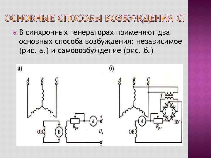 In synchronous generators, two main excitation methods are used: independent (Fig. A.) and self-excitation (Fig. B.)
 With independent excitation, the excitation winding is powered by a DC generator with an independent excitation winding located on the rotor shaft of the synchronous generator and rotating with it (high power). With self-excitation, the excitation winding is powered by the synchronous generator itself through a rectifier (low and medium power).
 With the help of the prime mover, the rotor inductor rotates. The magnetic field is located on the rotor and rotates with it, so the speed of rotation of the rotor is equal to the speed of rotation of the magnetic field - hence the name synchronous machine.
 When the rotor rotates, the magnetic flux of the poles crosses the stator winding and induces an EMF in it according to the law of electromagnetic induction: E = 4, 44*f*w*kw*F, where: f is the frequency of the alternating current, Hz; w is the number of turns; kw – winding coefficient; Ф - magnetic flux. The frequency of the induced EMF (voltage, current) of the synchronous generator: f =p *n/60, where: p is the number of pairs of poles; n is the rotor speed, rpm.
 Replacing in: E \u003d 4, 44 * (n * r / 60) * w * kw * F and, having determined that: 4, 44 * (r / 60) * w * kw - refers to the design of the machine and creates a design coefficient: C \u003d 4. 44 * (p / 60) * w * kw. Then: E \u003d SE * n * F. Thus, as with any generator based on the law of electromagnetic induction, the induced EMF is proportional to the magnetic flux of the machine and the speed of rotation of the rotor.
 Synchronous machines are also used as an electric motor, especially in high power installations (over 50 kW).
 To operate a synchronous machine in motor mode, the stator winding is connected to a three-phase network, and the rotor winding is connected to a direct current source. As a result of the interaction of the rotating magnetic field of the machine with the direct current of the excitation winding, a torque M arises, which entrains it at the speed of the magnetic field.
 To connect the generator to the network, it is necessary: the same phase sequence in the network and the generator; equality of mains voltage and generator EMF; equality of generator EMF frequencies and mains voltage; turn on the generator at the moment when the generator EMF in each phase is directed opposite to the mains voltage. Failure to comply with these conditions leads to the fact that at the moment the generator is connected to the network, currents arise that can be large and disable the generator.
According to the method of excitation, synchronous machines are divided into two types:
Excitation of an independent kind.
Self-excitation.
With independent excitation, the circuit implies the presence of a sub-exciter that feeds: winding of the main exciter, rheostat for adjustment, control devices, voltage regulators, etc. In addition to this method, excitation can be carried out from a generator that performs an auxiliary function, it is driven by a synchronous or asynchronous type motor.
For self-excitation , the winding is powered through a rectifier operating on semiconductors or ionic type.
For turbo and hydro generators, thyristor excitation devices are used. The excitation current is regulated automatically, using an excitation regulator, for low-power machines, the use of adjusting rheostats is typical, they are included in the excitation winding circuit.
27. Advantages and disadvantages of a synchronous motor.
A synchronous motor has several advantages over an asynchronous one:
1. High power factor cosФ=0.9.
2. The possibility of using synchronous motors in enterprises to increase the overall power factor.
3. High efficiency, it is more than that of an asynchronous motor by (0.5-3%), this is achieved by reducing losses in copper and large CosФ.
4. Possesses the big durability caused by the increased air gap.
The torque of a synchronous motor is directly proportional to the voltage to the first power. That is, the synchronous motor will be less sensitive to changes in the magnitude of the mains voltage.
Disadvantages of a synchronous motor:
1. The complexity of the launch equipment and the high cost.
2. Synchronous motors are used to drive machines and mechanisms that do not need to change the speed, as well as for mechanisms in which the speed remains constant with a change in load: (pumps, compressors, fans.)
Starting a synchronous motor.
In view of the absence of a starting torque in a synchronous motor, the following methods are used to start it:
2. Asynchronous motor start.
1. Start with auxiliary motor.
The start-up of a synchronous motor with the help of an auxiliary motor can only be carried out without a mechanical load on its shaft, i.e. practically idle. In this case, for the start-up period, the motor temporarily turns into a synchronous generator, the rotor of which is driven by a small auxiliary motor. The stator of this generator is connected in parallel to the network in compliance with all the necessary conditions for this connection. After the stator is connected to the network, the auxiliary drive motor is mechanically switched off. This starting method is complex and has an auxiliary motor in addition.
2. Asynchronous motor start.
The most common way to start synchronous motors is asynchronous start, in which the synchronous motor turns into an asynchronous motor for the duration of the start. To enable the formation of an asynchronous starting torque, a starting short-circuited winding is placed in the grooves of the pole pieces of a salient-pole motor. This winding consists of brass rods inserted into the grooves of the tips and short-circuited at both ends with copper rings.
When the engine is started, the stator winding is connected to the AC network. The excitation winding (3) for the start-up period is closed to some resistance Rg, fig. 45, key K is in position 2, resistance Rg = (8-10) Rv. At the initial moment of starting at S = 1, due to the large number of turns of the excitation winding, the rotating magnetic field of the stator will induce an EMF Ev in the excitation winding, which can reach a very large value, and if the excitation winding is not turned on for resistance Rg during start-up, insulation breakdown will occur.
Rice. 45 Fig. 46.
The process of starting a synchronous motor is carried out in two stages. When the stator winding (1) is connected to the network, a rotating field is formed in the motor, which will induce an EMF in the short-circuited rotor winding (2). Under the action, which will flow in the rods current. As a result of the interaction of a rotating magnetic field with a current, a torque is created in a short-circuited winding, as in an asynchronous motor. Due to this moment, the rotor accelerates to slip close to zero (S=0.05), fig. 46. This ends the first stage.
In order for the motor rotor to be drawn into synchronism, it is necessary to create a magnetic field in it by turning on the DC excitation winding (3) (by switching the key K to position 1). Since the rotor is accelerated to a speed close to
to synchronous, then the relative speed of the stator and rotor fields is small. The poles will smoothly find each other. And after a series of slips, the opposite poles will be attracted, and the rotor will be drawn into synchronism. After that, the rotor will rotate at a synchronous speed, and its rotational speed will be constant, fig. 46. This ends the second stage of the launch.
Synchronous machines use several excitation systems.
Electric machine excitation system with direct current exciter (Fig. 1). In this system, a special direct current generator (DCG) called an exciter is used as a source.
Excitation systems are divided into two types - direct and indirect. In direct excitation systems, the exciter armature is connected to the shaft of the synchronous machine. In indirect excitation systems, the exciter is driven by a motor that is fed from the auxiliary busbars of the power plant or an auxiliary generator. The auxiliary generator can be connected to the shaft of the synchronous machine or operate independently. Direct systems are more reliable, since in case of emergency situations in the power system, the exciter rotor continues to rotate together with the rotor of the synchronous machine and the field winding does not immediately de-energize.
Rice. 1. Electromachine excitation system: LG LE- exciter winding G.E.; R Ш1 - adjusting resistance
The classical excitation system of synchronous machines consists of an exciter in the form of a parallel excitation generator on a common shaft with a synchronous machine (electric machine exciter). In low-speed machines with a power of up to 5000 kW, in order to reduce the mass and cost of exciters, the latter are sometimes connected to the shaft of a synchronous machine using a V-belt drive. Hydrogenerators also usually have an exciter on the same shaft as the generator.
To extinguish the magnetic field, a field extinguishing machine (AGP) is used, which consists of contactors K1, K2 and quenching (discharge) resistor R P. Field blanking is carried out in the following order. When the contactor is on K1 contactor turns on K2, closing the excitation winding to a resistor , where R B- excitation winding resistance. Then the contactor opens. K 1, and the current in the excitation winding circuit of the generator begins to decrease (fade out) with the time constant ( LB- excitation winding inductance) in accordance with the equation (Fig. 2).
The excitation current could be reduced to zero by switching off only one contactor To 1 without quenching resistor included R P. The excitation current in this case would disappear almost instantly. But an instant break in the excitation circuit is unacceptable, because due to the high inductance of the excitation winding, a large self-induction emf would be induced in it, exceeding the rated voltage by several times, as a result of which a breakdown of the insulation of this winding is possible. In addition, the contactor To 1, a break would release a large amount of energy stored in the magnetic field of the excitation winding, and due to a large arc, the contacts would be destroyed. For large machines, the damping of the excitation current in the presence of a quenching resistor occurs with a time constant of about 1 s.
The excitation is forced by shunting the resistor R W1 included in the excitation circuit of the exciter.
Rice. 2. Attenuation of the excitation current when the field is quenched
However, powerful low-speed generators with n p\u003d 60-150 rpm, the dimensions and cost of the exciter due to its significant power and low speed are large. In addition, low-speed exciters, due to their large size, have a large electromagnetic inertia, which reduces the efficiency of automatic control and excitation forcing. Therefore, excitation systems are also used in the form of a separate high-speed unit ( n p\u003d 750-1500 rpm), consisting of an asynchronous motor and a DC generator. In this case, the asynchronous motor receives power from a special auxiliary synchronous generator located on the same shaft as the main hydro generator, and in some cases from the auxiliary tires of the hydro station or from the outputs of the main hydro generator. In the latter case, the excitatory unit is subject to the influence of accidents in the power system (short circuits, etc.), and therefore, to increase its reliability, drive asynchronous motors are performed with an increased maximum torque (M max ≥4 M n) , and sometimes these units are also equipped with flywheels. Standby excitation units of power plants are also made in the form of separate excitation units, which serve to back up generators' own exciters in case of accidents and malfunctions.
Turbine generators with power up to P n = 100 MW also usually have exciters in the form of DC generators on their shaft. However, when P n > 100 MW, the power of the exciters becomes so large that their performance at n p= 3000-3600 rpm, according to the conditions of switching reliability, it turns out to be difficult or even impossible. In this case, different solutions are applied. For example, exciters with a rotation speed n p\u003d 750 - 1000 rpm, connected to the turbogenerator shaft using a gearbox, as well as excitatory units with asynchronous motors powered from the busbars of the station or from the generator outputs.
The exciter power is usually 0.3-3% of the synchronous generator power. It is driven by the shaft of a synchronous generator. Excitation current of a large synchronous machine I B is relatively large and amounts to several hundred and even thousands of amperes. Therefore, it is regulated using rheostats installed in the excitation circuit of the pathogen. The excitation of the exciter is carried out according to the scheme self-excitation(Fig. 1) or independent excitation from a special DC generator called sub-exciter(Fig. 3). The subexciter works with self-excitation, and the resistance of the resistor R W2 does not change during the operation of the generator.
Rice. 3. Electric machine excitation system with subexciter: LG- excitation winding of the synchronous generator; LE- Exciter winding G.E.; LA- exciter winding GEA
Compound excitation system with DC exciter (Fig. 4). In modern excitation systems, the principle of compounding is widely used, i.e., automatic change in the magnetizing excitation force when the load current of the synchronous generator changes. Since an alternating current flows in the armature winding of a synchronous machine, and a direct current flows in the excitation winding 2, semiconductor rectifiers are used in the compounding circuits of synchronous machines.
In the fig. 4 circuit diagram of compound excitation system with exciter DC exciter exciter winding 4 connected to the armature of the exciter 3 with rheostat 6 and, in addition, to rectifiers 9, powered by series transformers 7. Idle generator winding 4 receives power only from the anchor 3. As the generator load current increases 1 transformer secondary voltage 7 will grow, and even with a small load, this voltage, rectified by the rectifier 9, match the winding voltage 4. With further increase in load, the winding 4 will be fed from transformer 7 and, therefore, the current of this winding and the excitation current of the generator will increase with increasing load.
With an increase in the resistance of the installation rheostat 8 voltage supplied to the rectifiers 9, and the compounding action of the transformer 7 will increase. In case of short circuits, the compounding device performs excitation forcing.
Rice. 4. Excitation system with current compounding
The compounding action of the scheme in Fig. 4 depends only on the value of the load current and does not depend on its phase. Therefore, with an inductive load, this action is weaker than with a resistive load. Such compounding is called current compounding, and at the same time, the constancy of the voltage U within the range of normal loads, it is possible to maintain up to ± (5-10)%. Such accuracy for modern installations is insufficient, and therefore in the circuits of Fig. 4 an additional corrector or automatic voltage regulator // is used, which is connected with a transformer 10 with generator clamps, as well as with an adjusting rheostat 8. Regulator 11 responds to voltage changes U and current / and supplies direct current to the additional excitation winding of the exciter 5.
Excitation valve systems can be built for high power and are more reliable than electric machines. There are three types of valve excitation systems: self-excited, independent and brushless.
In a system with self-excitation (Fig. 6), the energy for excitation of a synchronous machine is taken from the armature winding of the main generator, and then converted by a static converter PU (thyristor converter) into direct current energy, which enters the excitation winding. The initial excitation of the generator occurs due to the residual magnetization of its poles.
Rice. 6. Valve excitation system of a synchronous generator with self-excitation: LG- excitation winding of the generator; PU- Converter with voltage regulator; TV- a voltage transformer that reduces the voltage supplied to the excitation winding; TA- current transformer, which serves to maintain the excitation voltage when the generator load changes
In an independent valve excitation system (fig. 7) energy for excitation is obtained from a special exciter GN, made in the form of a three-phase synchronous generator. Its rotor is located on the main generator shaft. The alternating voltage of the exciter is rectified and fed into the excitation winding.
A kind of independent valve excitation system is a brushless excitation system. In this case, an AC exciter armature with a three-phase winding is placed on the shaft of the main synchronous machine.
Rice. 7. Valve independent excitation system: GN - alternating current exciter (synchronous); LN - exciter winding; GEA - sub-exciter;
LA - subexciter excitation winding; PU - converting device with voltage regulator
The alternating voltage of this winding through a rectifier bridge mounted on the machine shaft is converted into a constant voltage and directly (without rings) is fed to the excitation winding of the main generator. The field winding of the exciter is located on the stator and receives power from the subexciter or voltage regulator.
. A feature of these machines is that they use permanent magnets to create a magnetic excitation field. Permanent magnets are most often placed on the rotor, making the machine contactless. Permanent magnet synchronous machines are widely used as small power generators and micromotors.
The disadvantages of such machines include the difficulty of regulating the magnetic flux, high cost, low power limit (due to the low mechanical strength of the permanent magnet rotor), as well as the increased mass of medium power machines.
Synchronous generators with permanent magnets are produced at a power not exceeding several tens of kilowatts. Synchronous motors with permanent magnets and asynchronous start are widely used. The rotors of such motors combine elements of a synchronous motor - permanent magnets and an asynchronous motor - a squirrel cage necessary for starting.
4. Synchronous machines with permanent magnet excitation
A feature of these machines is that they use permanent magnets to create a magnetic excitation field. Permanent magnets are most often placed on the rotor, making the machine contactless. Permanent magnet synchronous machines are widely used as small power generators and micromotors.
The advantages of machines with permanent magnets are the simplicity of design, the absence of sliding contact, high efficiency and less heating due to the absence of losses in the winding: excitation and sliding contact. The great advantage of these machines is also the absence of a direct current source for their excitation.
The disadvantages of such machines include the difficulty of regulating the magnetic flux, high cost, low limiting power (due to the low mechanical strength of the permanent magnet rotor), as well as the increased mass of medium power machines.
Synchronous generators with permanent magnets are produced at a power not exceeding several tens of kilowatts. Synchronous motors with permanent magnets and asynchronous start are widely used. The rotors of such motors combine elements of a synchronous motor - permanent magnets and an asynchronous motor - a squirrel cage necessary for starting.
Permanent magnets can have a radial and axial arrangement on the rotor. In the first case, magnet 1 has the shape of an asterisk (Fig. 7), a steel annular package 2 is pressed onto it, in the grooves of which the rods of a squirrel cage are located.
Rice. 7. Synchronous motor with a radial arrangement of permanent magnets on the rotor: 1 - permanent magnets; 2 - rotor package; 3 - stator
Interpolar slots are made in the steel of the annular package to reduce the leakage fluxes of magnets. In the second case, a rotor 2 is located on the shaft according to the type of rotor of an asynchronous motor, and permanent magnets 1 are placed on one or both sides of this package (Fig. 8). in this case, there is also a braking (generator) moment. The braking torque appears as a result of the interaction of the magnetic field of the excited poles of the rotor with the currents induced by it in the stator winding 3. In fig. 9 shows the curves of the asynchronous M a, brake M T and the resulting M moments of the motor during asynchronous starting.
Rice. 8. Synchronous motor with axial arrangement of permanent magnets on the rotor: I - permanent magnet; 2 - rotor package; 3 - stator
Rice. 9. Starting characteristics of the permanent magnet motor
The starting characteristics of motors with permanent magnets are worse than those of hysteresis motors, but they have better energy performance, increased overload capacity, and speed stability.
