Assembling a personal short-range radar. How to make an active radar detector with your own hands (jammer from cameras and radars) DIY portable radar
The Alexei Navalny Anti-Corruption Foundation managed to find out that the plane is used by the official not only for flights to business meetings, but also for taking his dogs to various international exhibitions and competitions. However, the joy of civil society about the prospects that opened up before it to identify servants of the people living beyond their means was short-lived - the services mentioned above turned off the ability to monitor the flights of the Deputy Prime Minister and his dogs, and they ignored all questions about the legality of such a decision.
What to do?
If commercial flight tracking services act on the side of the state and refuse to publish information about aircraft owned by officials, we citizens can get this data ourselves. Having spent about four thousand rubles on equipment and a couple of days of free time for assembly and installation, anyone can participate in the ADSBexchange.com independent aircraft tracking project.
How it works?
Each modern aircraft is equipped with a so-called ADS-B transponder - a device that transmits information about itself at a certain frequency in response to a request from a radar station (RLS) - a unique aircraft identifier, as well as data on location, flight speed and some others. The important thing here is that anyone can receive and decode this information by using freely available inexpensive household equipment - a USB DVB-T digital television receiver connected to a Raspberry Pi single-board computer with a decoder program running on it.
The decoded information about the aircraft in the line of sight of the receiver can be viewed locally, but to track the complete route of the aircraft from the origin to the destination, information received from the receivers from all intermediate points must be combined. This is exactly what the ADSBexchange.com service is intended for, creating, based on the data received from local receiving stations, a global flight map - Global Radar View, functionally similar to that of services such as PlaneFinder.net and FlightRadar24.com, but, unlike them, does not hide no information from end users about tracked aircraft. Here, for example, we can see that for the New Year holidays, the Deputy Prime Minister again flew to his dacha in Austria:

The more receiving stations connected to the service, the more complete the coverage is, and in the case of Russia the situation is still very sad - just look at the map and compare the number of stations we have with the number of stations in Europe.

But we have the power to change the situation! To do this, you just need to build your own receiving station and include it in the ADSBexchange network.
What is needed for this?
1 Raspberry Pi
The most popular single-board microcomputer in the world, there are several models that differ in memory size, processor frequency and a set of peripherals. For our purposes, any model with an Ethernet port on board will do, for example, Raspberry Pi 3 Model B:

You can buy together with a power supply and a case on Aliexpress at a price of about 3000 rubles, for example,. You can also search with domestic sellers, but the price, of course, will be significantly higher.
2. Memory card
The Raspberry Pi 3 requires a microSD memory card, older models use a full size SD card. The recommended volume is 8GB, the speed class is 10. Of the trusted manufacturers, I can recommend SanDisk or Transcend cards. The issue price is about 300 rubles.
3. USB DVB-T receiver
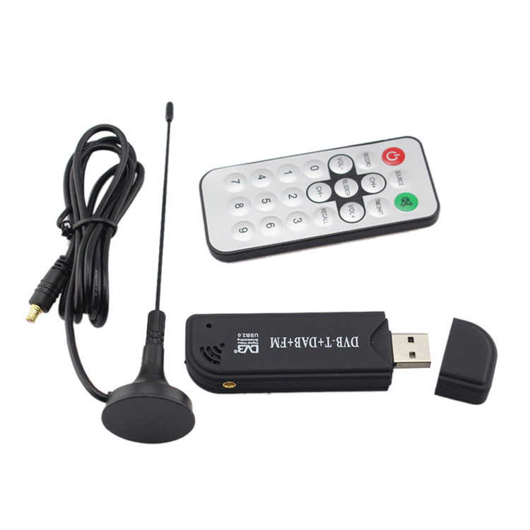
The keywords to search on Aliexpress are "RTL2832U R820T2", the price is about 500 rubles, for example, like this. You can search with local sellers, but a receiver that looks exactly the same on the outside may turn out to be built on other chips, so you need to check with the seller that it is the RTL2832U + R820T2 bundle that is inside.
4. Antenna
An antenna is included with the USB receiver, but, to put it mildly, it is poorly suited for receiving signals from aircraft transponders, so the reception radius with it will be small - several tens of kilometers at most. In order to get a radius of hundreds of kilometers, it will have to be replaced with a more suitable one. The easiest option is to replace the standard antenna pin with a three-element collinear antenna, which can be bent from copper or steel wire according to the following drawing (clickable):

You should get something like this:

The best option, which provides a maximum reception range of up to 400 km, is to use a coaxial collinear antenna.
Since the reception of radio signals from aircraft transponders is possible only within the line of sight, the antenna must be placed outdoors, ideally on the roof. To do this, you can use either a USB extension cable up to 5 meters long, placing only the receiver in a sealed box, or PoE (in this case, Raspberry Pi will also need to be placed in the box).
5. Soft
ADSBexchange currently uses a modified PiAware distribution. This distribution was developed by FlightAware, which also provides a commercial aircraft tracking service, but, alas, in its original form also hides information about private jets. This distribution is taken as the basis for ADSBexchange, as it is very easy to install and configure.
Step by step instructions for Windows:
- Download the distribution package https://www.adsbexchange.com/downloads/ADSBexchange-img-1.2.zip (868 MB) and save it on your computer.
- Unzip the ADSBexchange-img-1.2.zip file.
- Download the Win32DiskImager utility and run it as an administrator (to do this, right-click the file and select "Run as administrator").
- Select the ADSBexchange-img-1.2.img file.
- Insert the SD card into your computer's card reader.
- Select the letter designation of the SD card from the corresponding list.
- Click "record" and wait for the end for a few minutes.
- When finished, remove the memory card from the card reader and insert it into the Raspberry Pi.
- Connect all cables (USB power, Ethernet cable, USB receiver) to Raspberry Pi. At the same time, the red LED should be lit on the Raspberry Pi and the green LED should blink, and green and yellow near the Ethernet network connector.
- Wait a couple of minutes for the Raspberry Pi to boot up.
- Register a new account on the FlightAware website.
- Link the receiver to the created account.
- In the receiver settings ("My ADS-B" tab), edit the receiver location coordinates and the antenna installation height above ground level.
- After a while, the receiver should appear on the coverage map https://www.adsbexchange.com/active-feeds/ .
- The aircraft currently being tracked by your receiving station can be viewed by clicking on the "Web interface: view live data" link of the "My ADS-B" tab on the FlightAware website.
PROFIT!
Now your receiver participates in two flight tracking networks at once - ADSBexchange and, as a bonus, FlightAware. Distribute this instruction, help others build their own receiving stations, and Shuvalov's dog-plane will not be able to hide from the all-seeing eye of civil society!
Having the skills to work with microcontrollers, the radar can be made independently using microcircuits, a set of wires, an infrared sensor and other devices. You also need to have a diagram for further assembly.
You will need
- - Skills in working with radio engineering and microcontrollers.
Instruction
One of my students came up with the idea of creating some kind of radar to determine the distance. We continued its development and decided to introduce it into the course program as one of the projects.
After a couple of weeks of preparation, we finally decided how to start it and what might be needed for this. The design didn't have to be very advanced; we set the difficulty level to medium. Below is an example of using a narrow band personal radar. He was supposed to look a little funny, so you can laugh!
Description and purpose of the project
The goal of the project was to create a functioning radar. The system is only required to measure the distance at a 90 degree angle, as shown in the example above. Depending on the selected sensor, the system operates within 4-30 cm, 20-150 cm and 1-5.5 m.
The results of the project will influence subsequent developments in which we will try to integrate radar for mobile robot navigation in natural conditions.
Electronic parts
- Voltage regulator LM7805 5V
- Microcontroller PIC18F452
- IR Sensor GP2D120
- Quartz resonator at 4 or 8 MHz
- Switch
- Capacitor
- 30-pin connector
- 5 triggers 74LS373
- Bread board
- Solder
- 36 indicators
- Wire 30 AWG
- Wire Tools
- soldering iron
Detailed parts list
You may or may not know everything about the above details, so to help make sense of them, a picture of every detail has been included. There were three new objects that were not previously specified in the project: a servo system, and IR sensors. Description and IR sensors coming soon; as for 74HCT373, a brief overview will be given below. You can always check the IC specification by simply searching for "74HCT373".

An eight-bit microcircuit containing a tri-stable flip-flop. Simply put, this chip is capable of storing 8 bits of digital logic and holding it in memory until it is erased or changed using the LE-Latch Enable pin.
Work principles
- Control terminals LE and OE
- 8 Data entry D0-D7
- 8 Data output D0-D7
Power (Vcc & GND.)
Output Activation (OE) allows Q0-Q7 to output data currently in D-flip-flops.
Trigger Activation (LE) allows the data contained on D0-D7 to be overwritten to the D-trigger.
Circuit overview
The scheme for this project is much more complicated than the previous ones. There are 4 main advantages in our development.
- We will be able to program images from the developed board.
- We will control the servo system.
- We will be taking data from the IR distance sensor.
- We will set 36 LEV indicators to display the data output received from the IR sensor.
Circuit Characteristics
Nutrition
- Power is supplied via a 9V battery connected to the LM7805 with a 1uF capacitor connected to the pin/ground to provide uninterrupted DC power to the LM7805.
- Program cycle
- Programming is done by connecting two connectors from the controller to the programmer, giving the first programmer connector access to MCLR*/Vpp-Pin1 on the controller. For safety reasons, a rectifier diode is installed.
- IR Distance Sensor
- The IR Sensor uses one controller connector PIN 2 - RA0. The analog capabilities of this pin are used to obtain the ADC value, since only the analog signal is taken from the IR sensor. This value tells if there is something within the sensor's coverage radius.
LED indication
There are 40 LED indicators in total. Each 74HCT373 chip controls up to 8 LEDs; since 40/8=5 we need 5 74HCT373 circuits to drive all 40 indicators. It should be noted in the diagram that one data bus is used for all 5 chips.
Theory
This development uses three main instruments to create a personal radar. The IR sensor is connected to the microcontroller, and then output to the indicator segment. A visual demonstration of this process is provided:
Using different sensors
An important aspect of the accuracy of the IR sensors used in this project is that they have the same voltage characteristics, so this program is compatible with all indicators. The only thing you need to know is how the sensor is used to determine the distance displayed on the indicators.
Usage
So, let's take a look at the final form of the device:

This is the appearance of the assembled device. Let's move on to the next section and continue assembling the instrument.
The plastic housing at the bottom of the picture was not mentioned in the parts list. This is a common case that can be purchased from any electronics manufacturer or retailer. First of all, you need to drill 36 holes for the indicators in the circuit and fix the indicators in them. An anchoring agent was used before inserting the indicators into the holes.

After the panel is soldered, we start connecting the circuit. Each wire must be connected through a small hole in the case.

The figure above shows the view of the panel at an early stage. At the beginning of connecting the wires, there is an accumulation of a huge number of them, for example, like this:


The final touch in the development of a personal radar is the ability to use it online. Use wires with a length of 2-4 meters when connecting the servo system and the IR sensor. We make a hole in front of the case for these wires:
Having finished with the assembly, let's move on to the software part of the development. This is certainly a more subtle part of the design than even the wiring.
The software for this instrument consists of three main parts:
- Servo Control
- LED indication control
- input A/D/
Since all the software in this project won't fit on one page, what the parts are and how they work will be explained.
Servo Control
The servo system is controlled by timers and interrupts. With two separate interrupts fired simultaneously to create the desired sound, a 50 GHz signal is generated and the servo pointer moves in small steps to adjust the creaky sound.
Adjustment of LED indication.
The indicators are controlled by triggers 74LS373/74HCT373. The system constantly updates the trigger data displayed on the indicators.
A/C Input
The IR sensor provides analog output. A converter is used to determine the voltage value, indicating that the object has gone to a distance outside the IR sensor's coverage area.

The assembly and configuration of the device is completed - you need to test it. Depending on the sensor you are using, the indication will be different. Sensors to choose from GP2D120, GP2Y0A21YK and GP2Y0A700K0F.
Data and observations
The first radar test will be a close range test. Tin cans were used as obstacles.
On the second video (on the first page) indicators 20 cm - 150 cm and 1 m - 5.5 m are tested, allowing to overcome more serious obstacles. Look to understand what is at stake.
Two videos will demonstrate the operation of the sensor, however, with self-assembly, slight difficulties are possible, which will be described in the conclusion.
ABOUT personal radar overview
Assembling and setting up this device takes a little time. This is a project that you can do in a day, and it already has a niche in application, but over time, additional difficulties will arise. IR sensors may become unreliable, output results may be poor due to environmental influences.
Actions to be taken
To increase the coverage radius of the sensor, it is planned to use ultrasonic sensors, equivalent to the “sound sensors” described above, transmitting data on the distance from you to the object. The range of ultrasound is wider than that of infrared radiation, and it is more reliable in adverse conditions.
Conclusion
The project was a fascinating study of IR sensors. It demonstrates that the results can be obtained and used realistically. Many further projects can be developed from this.
Practice shows that quite often everything home-made, if done with high quality, works best of all serial. This is due to the fact that manual assembly, unlike mass assembly, is performed most carefully. In addition, with your own hands you can collect something that is not available for sale at all. One of these tasks is the task of how to make a radar. There are radar detectors and radar detectors on sale, but it is almost impossible to buy a radar itself, such as the one used by the traffic police. This special technique is not commercially available, so it is virtually unavailable, regardless of its price. Although if it were on sale, then it was the price of modern electronic systems designed to control the speed of cars by the traffic police that would become the main obstacle to its acquisition.
When thinking about how to include a radar in the number of do-it-yourself electronic devices, it is necessary, first of all, to understand where to get the components for assembling this rather complex device. The components include a good digital video camera and a device for laser measurement of the speed of moving objects, which can be purchased in specialized stores for aeromodelling enthusiasts. In addition, you will need patch cords that will allow you to transfer the laser speedometer readings and the image from the video camera to a computer, and then record these readings along with an image of a moving car. You will also need a housing that solves the problem of how to install a radar consisting of two separate named electronic devices, so that both the camera and the laser speed meter "look" at the same object.
The laser speed meter works on the principle of fixing the time after which the laser beam, pulsed by the device, reflects from the surface of a moving object, and returns to the device. Such fixation when measuring speed is carried out up to 10 times, after which the device displays on its display the result of measuring the speed of the object at which it was aimed. In fact, this is the radar, and the camera is needed only for reliable recording of the results. It remains to solve the question of how to connect the radar to the computer. This requires a USB cable as this instrument has standard settings for transferring information to a computer. In the same way, a camcorder is connected to the computer through another USB port using a second cable.
The camera and the device are placed together in a housing that fixes them rigidly and allows both devices to "look" at the same moving object. All devices turn on simultaneously, then the image received from the camera in on-line mode remains in the lower open window, and the image received from the laser speed meter is superimposed on top of it in another window of a smaller size. The Camtasia Studio program is installed on the computer, which allows you to record everything that happens on the monitor, this program is configured according to the instructions attached to it and starts in recording mode. As a result, it becomes clear how to use the radar: turning everything on together, point the body with the camera and the meter at a moving object, and then record combined images of the moving object and speed readings from the computer monitor.
Didn't know how to set up or optimize the radar in CS GO? In this topic, we will just take a look at the radar settings in CS Global Offensive. What is needed to set up the radar? Everything is done very simply, no additional software is required to download, all you need is:
Turning on the console
If you have problems opening the console, then follow the instructions below:
- Launch CS:GO;
- Settings → Game Settings;
- Enable Developer Console → Yes;
- Settings → Keyboard / Mouse;
- Scroll to the very bottom and you will see "Open Console" turns on " ` "- you can set any of your keys.
Now you can start setting up!
Radar setup
The first thing I would advise you is to create a game with bots so that they can't kill you and set up the radar directly in the game. Let's start:
Enable/Disable Radar
To turn on radar, you must enter the drawradar command in the console;
In order to hide radar uses the console command hideradar ;
cl_hud_radar_scale
This command controls the size of the radar on your screen.
 |
|
| cl_hud_radar_scale "0.8" | cl_hud_radar_scale "1.3" |
| Minimum: "0.8" // Maximum: "1.3" | |
cl_radar_always_centered
The player is always at the center of the radar. At first glance, it may seem that there is not much difference, but the plus is obvious - when you are in the corner of the map, you have a greater view of the terrain on the radar than if you were in the center of the radar.
 |
 |
| cl_radar_always_centered "0" | cl_radar_always_centered "1" |
| Two variables are available for selection, either 0 or 1 | |
cl_radar_icon_scale_min
This command changes the size of the various icons on your radar.
| cl_radar_icon_scale_min "0.4" | cl_radar_icon_scale_min "1.0" |
| Minimum: "0.4" // Maximum: "1.0" | |
cl_radar_rotate
Enable or disable radar rotation. Those. if disabled, the map on the radar will always be in the same position.
 |
 |
| cl_radar_rotate "0" | cl_radar_rotate "1" |
| Can be set to either 0 or 1 | |
cl_radar_scale
Change the scale of the map displayed on the radar.
 |
 |
| cl_radar_scale "0.25" | cl_radar_scale "1.0" |
| Minimum: "0.25" // Maximum: "1.0" | |
cl_hud_bomb_under_radar
This command toggles on and off the display of the bomb icon when you are carrying one or when you are not.
Dynamic Radar Resizing
There are cases in which the scale of the map on the radar needs to be increased or vice versa, reduced. This can be done using the bind below:
Bind "KP_plus" "incrementvar cl_radar_scale 0.25 1.0 0.05";//increase the size of the radar bind "KP_minus" "incrementvar cl_radar_scale 0.25 1.0 -0.05"; //reduce the size of the radar
This bind allows the button + or - dynamically resize the radar when you press. Buttons can be any of your choice.
