Balcony Magnetic Loop - diagrams, descriptions. Experiments with magnetic loop antennas Tube for making a magnetic loop antenna
Magnetic loop home antenna is a great alternative to classic outdoor ones. Such designs allow you to transmit signals up to 80 m. For their manufacture, coaxial cable is most often used.
The classic version of the magnetic loop antenna
A frame magnetic installation is a subtype of small-sized amateur antennas that can be installed anywhere in a populated area. Under the same conditions, the frames show a more stable result than analogues.
In home practice, the most successful models of popular manufacturers are used. Most of the circuits are given in the amateur literature of radio engineers.

Indoor Magnetic Coaxial Loop Antenna
Do-it-yourself antenna assembly
Materials for manufacturing
The main element is a coaxial cable of several types, 12 m and 4 m long. To build a working model, you also need wooden planks, a 100 pF capacitor and a coaxial connector.
Assembly
A magnetic loop antenna is constructed without special training and knowledge of technical literature. Adhering to the assembly order, you can get a working device the first time:
- connect wooden planks with a cross;
- cut grooves in the boards, corresponding to the radius of the conductor with a depth;
- drill holes on the planks at the base of the cross to secure the cable. Cut three grooves between them.
Accurate dimensional exposure allows you to build a structure with high radio frequency reception.
Form of magnetic frames
A magnetic antenna made of coaxial cable is a loop of conductor that is connected to a capacitor. The loop, as a rule, has the form of a circle. This is due to the fact that this form increases the efficiency of the structure. The area of this figure is the largest in comparison with the area of other geometric bodies, therefore, the signal coverage will be increased. Manufacturers of goods for radio amateurs produce exactly round frames.

Installation of the structure on the balcony
In order for the devices to work on a specific wavelength range, loops of various diameters are constructed.
There are also models in the form of triangles, squares and polygons. The use of such structures is due in each case to different factors: the location of the device in the room, compactness, etc.
Round and square frames are considered single-turn, because. the conductor is not twisted. To date, special programs such as KI6GD allow you to calculate the characteristics of only single-turn antennas. This type has proven itself well for working on high-frequency ranges. Their main disadvantage is their large size. Many specialists tend to work at low frequencies, which is why the magnetic frame installation is so popular.
Conducted comparative calculations of several circuits with one, two or more turns, under similar operating conditions, showed the dubious efficiency of multi-turn designs. The increase in turns is most expedient only to reduce the dimensions of the entire device. In addition, for the implementation of this scheme, it is necessary to increase the consumption of the cable, therefore, the cost of homemade unreasonably increases.
Magnetic frame sheet
For maximum efficiency of the installation, one condition must be achieved: the loss resistance in the frame web must be comparable to the radiation resistance of the entire structure. For copper thin tubes, this condition is easily satisfied. For coaxial cables of large diameter, this effect is more difficult to achieve due to the high resistance of the material. In practice, both types of structures are used, because. other types perform much worse.
receiving frames
If the device performs exclusively the function of a receiver, then ordinary capacitors with solid dielectrics can be used for its operation. Receiving frames to reduce the size are multi-turn (made of thin wire).
For transmitting devices, such designs are not suitable, because. the action of the transmitter will work to heat the installation.
Coaxial cable braid
The braid of the magnetic frame gives greater efficiency than copper tubes and a thickening of the conductor diameter. For home experiments, models in a black plastic shell are not suitable, because. it contains a large amount of soot. During operation, metal parts with strong heating of the shell emit chemical compounds harmful to humans. In addition, this feature reduces the transmission signal.

Coaxial cable SAT-50M made in Italy
This type of coaxial cable is only suitable for large antennas, as their conductor radiation resistance fully compensates for the input resistance.
Impact of external factors
Due to the physical properties of coaxial cables, the antennas are not affected by temperature and precipitation. Only the shell created by external factors - rain, snow, ice - can be negatively affected. Water has higher losses than cable at high frequencies. As practice shows, it is possible to use such structures on balconies for several decades. Even in severe frosts, there is no significant deterioration in reception.
To increase reception, it is better to place magnetic devices made of coaxial cable in rooms or places of reduced exposure to precipitation: under roof peaks, on protected parts of open balconies. Otherwise, the device will work primarily to heat the environment, and only then to receive and transmit signals.
The main condition for stable operation is the protection of the capacitor from external influences - mechanical, weather, etc. With prolonged exposure to external factors, an arc may form due to high-frequency voltage, which, when overheated, quickly leads to a tap from the circuit or failure of this part.
Frames for high-frequency ranges are horizontal. For low-frequency, with a height of more than 30 m, it is advisable to build vertical structures. For them, the installation height does not affect the reception quality.
Device Location
If this mechanism is located on the roof, then one condition must be provided - this antenna must be higher than all the others. In practice, it is often impossible to achieve ideal placement. The magnetic frame installation is quite unpretentious to the close location of third-party objects and structures - ventilation towers, etc.
The correct location is on the roof with the core in the distance so that there is no absorption of the signal by large models. In view of this, when installed on a balcony, its efficiency decreases. This arrangement is justified in cases where conventional receivers do not work correctly.
Synchronization of frame and cable
Coordination of parts is achieved by placing a small inductive loop in a large one. For symmetrical connection, a special balancing transformer is included in the device. For unbalanced - connect the cable directly. The antenna is grounded at the point where the cable is attached to the base of the large circle. The deformation of the loop helps to achieve a more accurate setting of the device.

Modification of a coaxial cable device
Pros and cons of the device
Advantages
- low cost;
- ease of installation and maintenance;
- availability of raw materials;
- installation in small rooms;
- durability of the device;
- effective work near other radio devices;
- no special requirements to achieve high-quality reception (such devices work stably both in summer and winter).
disadvantages
The main disadvantage is the constant adjustment of the capacitors during the change of operating range. The noise level is reduced by turning the structure, which can be extremely difficult during operation due to the geometric shapes and arrangement of wooden planks. Due to radiation at close range, information is transmitted from magnetic tapes (when the tape recorder is turned on) to devices with inductors (TVs, radios, etc.) even when the antennas are turned off. The level of interference can be reduced by changing the location of the device.
During operation, do not touch the metal parts, due to strong heat, you can get burned.
We do it ourselves. Video
How to make a broadband active antenna with your own hands, you can learn from this video.
The magnetic loop antenna is the most cost effective solution for home use. The main advantages are operation at different frequencies, ease of assembly and compactness. A well-made device can receive and transmit an excellent signal over a fairly long distance.
At the mention of a magnetic antenna, they immediately fill the memory of structures on a ferrite rod, partly correctly. Varieties of the same type of device. A loop antenna is called magnetic, the perimeter of which is much smaller than the wavelength. The well-known zigzags, bikvadrat (synonymous words) are relatives of the technology in question. Antennas on a magnetic base have nothing to do with it. Just a way to mount. The magnetic base for the antenna securely holds the device on the roof of the car. Let's talk today about a special design. The beauty of magnetic antennas: it is possible to provide a relatively large gain at relatively long wavelengths. The size of the magnetic antenna is small. Let's discuss the title, tell you how a do-it-yourself magnetic antenna can be made.
Magnetic loop antenna
Magnetic Antennas
The theory says: in an oscillatory circuit of an inductor, a capacitor, radiation does not occur. Closed, the wave oscillates at the resonant frequency arbitrarily, damping due to the presence of active resistance. The circuit elements, inductance, capacitance, have a purely reactive (imaginary) impedance. Moreover, the size depends on the frequency according to a simple law. Something like the product of the circular frequency (2 P f) by the value of the inductance or capacitance, respectively. At a certain value, the opposite imaginary components become equal. As a result, the impedance becomes purely active, ideally zero.
In reality, the beats are attenuated; in practice, each circuit is characterized by a quality factor. Recall that the impedance consists of a purely active (real) part (resistors), imaginary. The latter include capacitances whose resistance is imaginary negative and inductances with positive imaginary resistance. Now imagine that in the circuit of the capacitor plates they began to part until they were at opposite ends of the inductance. It is called a vibrator (dipole) Hertz, is a kind of shortened half-wave, other types of vibrators.
If we turn the coil into a single ring, we get the simplest magnetic antenna. Simplified interpretation, approximately correct. The signal is taken from the opposite side of the capacitor through a field-effect transistor amplifier. Provide high sensitivity of the device. Well, an antenna on a ferrite rod is considered a kind of magnetic, only rings instead of one host. This type of device was named for its high sensitivity to the magnetic component of the wave. When working on transmission, it is generated, generating a response of the electric field.
The directivity maximum corresponds to the axis of the rod. Both directions are equal. Due to the small perimeter of the loop antenna relative to the wavelength, the resistance is quite low. Not just 1 ohm, fractions of an ohm. Let's estimate the value approximately by the formula:
R = 197 (U / λ) 4 ohm.
Under U is understood the perimeter in meters, similarly - the wavelength λ. Finally, R is the resistance to radiation, do not confuse with the active, shown by the tester. The parameter is used when calculating the amplifier for load matching. Therefore, for ferrite antennas, you need to multiply the value by the square of the number of turns.
Properties of magnetic antennas
Let's see how to make a magnetic antenna yourself. First determine the circumference and capacitance of the trimmer capacitor. The features of the magnetic antenna are as follows: the design requires coordination without fail. A distinctive feature is the incredible number of options for carrying out this operation, a separate topic of conversation emerges.
The length of the perimeter of the magnetic antenna ranges from 0.123 - 0.246 λ. If you want to cover the range, then you need to choose the right capacitor. In free space, the magnetic antenna pattern in the form of a torus is observed by placing the coil parallel to the ground. The polarization will be linear horizontal. This is a good option for receiving TV broadcasts. Disadvantage: the angle of elevation of the petal depends on the height of the suspension. It is believed that for the distance to the Earth λ, the figure will be 14 degrees. Impermanence is considered a negative quality. For radio, magnetic antennas are often used.
The gain is 1.76 dBi, 0.39 less than a half-wave vibrator. The size of the latter for the frequency will be tens of meters - where can you put a whopper. Draw your own conclusions. The magnetic antenna is small (perimeter is 2 meters for a wavelength of 20 meters, less than a meter across). For comparison, at a frequency of 34 MHz, which is well known to truckers thanks to walkie-talkies, the wavelength is 8.8 meters. It is known that a good half-wave vibrator will accommodate a rare Kamaz. By the way, earlier they gave a description of the design of the loop antenna formed by the rubber gasket of the rear window of a VAZ car. With small dimensions, the device worked quite well.
By the way, the design is considered more pragmatic than typical car whip antennas, where tuning is carried out by changing the inductance. There are fewer losses. The radiation pattern covers high elevation angles, touching the vertical. In the case of a whip antenna, this is not possible.
How to choose the right circumference. As the increase increases, the gain increases. Must satisfy the condition above, be as large as possible. Sometimes you need to cover the frequency range. Growing the perimeter increases the bandwidth of the device. With a typical channel width of 10 kHz, it makes no sense. Neighboring broadcaster carriers will be automatically cut off. More is not necessarily better. For the sake of amplification, fuss was started. The antenna is chosen by the maximum perimeter, providing the required selectivity.
Now the main question: to determine the capacity. So that parallel to the inductance of the loop form a resonance according to the well-known school formula. Determination of contour parameters according to the expression:
L = 2U (ln(U/d) – 1.07) nH;
U and d are the length of the coil, the diameter. Trick. U \u003d P d, therefore, instead of the ratio, you can take the natural logarithm of the number Pi. Whether the author's mistake, we do not undertake to say. Perhaps, the fact is taken into account that the tuning capacitor takes away part of the length, the amplifier ... We find the capacitance by inductance from the expression for the resonance of the circuit:
f = 1/ 2P √LC; where
C \u003d 1 / 4P 2 L f 2.
C \u003d 25330 / f 2 L,
where f is the resonant frequency in MHz and L is the inductance in µH.

Receiver Antenna
As for the method of removing the signal, we do this from the side of the trimmer capacitor on both sides, or from the opposite side of the circular loop. In the latter case, it is recommended to introduce control of the capacitor using a servo motor at a distance, we believe that this will seem very far-fetched to most readers, there are not so many radio amateurs in the world who are confident in the need for a magnetic antenna made by their own hands.
What are magnetic antennas
Magnetic antennas are not always round (ideal shape). There are octagonal, square. Readers guessed it: Bisquare WiFi belongs to the latter category, and the frame is doubled. It happens that more contours increase the gain in one plane of the radiation pattern. Given the fact that the antenna efficiency is calculated by the formula:
Efficiency = 1 / (1 + Rp / R),
We see the need to reduce the loss resistance Rp to a minimum. Otherwise, the performance of the device drops sharply. In practice, it means little, making antennas of gold and silver to catch NTV is unrealistic. In the named aspect, aluminum, copper will go, the latter is preferable. For magnetic antennas, an air-gap capacitor with large plates is suitable. Try to do quality soldering.
Example. The perimeter is one tenth of λ, so the radiation resistance is 0.02. Now readers can see how hard you have to try to bring the efficiency to 50%. The loss resistance in this case does not exceed 0.02 Ohm. To achieve this result, take a thick copper core. With an increase in the cross section of the conductor, the resistivity decreases.
The circuit has a high quality factor (low losses), it turns out that the resonance voltage is much higher than with a frequency deviation. Therefore, the bandwidth of the magnetic antenna is not very wide, the device will need to be adjusted. It is done with a capacitor. We hope that we answered the question of how to make a magnetic antenna. Play the Serve: Surprise your home with confident signal reception in any weather.
This post is for beginners.
radio amateurs and for those who do not have access
on the roof of your house. Sushko S.A. (ex. UA9LBG)
Magnetic antennas (Magnetic Loop) type-ML due to their small size are becoming increasingly popular. All of them can be placed on balconies and window sills. It is undeniable that single-turn magnetic antennas with a vacuum capacitor and a communication loop have won classical popularity, with the help of which it is possible to conduct radio communications even with other continents.
Two-frame antennas in the form of a figure eight relatively recently began to appear among radio amateurs, although at the dawn of the advent of CBS communications in Russia, such antennas were practiced with some success in car radio security systems in the 27 MHz band, see Fig. 1.a. The car antenna consisted of two identical frames (loops) L1; L2 and a common resonant capacitor C1, standing in the antinode of the voltage. With an antenna perimeter of about 5 meters, radio amateur Sterlikov A. ( RA9SUS) conducted communications with 36 countries with a power of up to 30 watts. The antenna was powered directly from the coaxial cable. And such antennas have been practiced since the late 60s, early 70s of the last century. The equivalent circuit of such an antenna is shown in Fig. 1.b.
Although single-turnMLare currently widely used among radio amateurs, a feature of the two-turn one is that its aperture is twice as large as that of the classical one. Capacitor C1 can change the resonance of the antenna with a frequency overlap of 2-3 times, and the total perimeter of the circle of two loops ≤ 0.5λ. This is commensurate with a half-wave antenna, and its small radiation aperture is compensated by an increased quality factor. Coordination of the feeder with such an antenna is best done through inductive or capacitive coupling.
Theoretical digression: The double loop can be considered as a mixed oscillatory systemLL andLC systems. Here, for normal operation, both arms are loaded on the radiation medium synchronously and in phase. If a positive half-wave is applied to the left shoulder, then exactly the same is applied to the right shoulder. The self-induction EMF that originated in each arm will, according to the Lenz rule, be opposite to the induction EMF, but since the induction EMF of each arm is opposite in direction, the self-induction EMF will always coincide with the direction of the induction of the opposite arm. Then the induction in the coil L1 will be summed up with the self-induction from the coil L2, and the induction of the coil L2 - with the self-induction L1. Just as in the LC circuit, the total radiation power can be several times greater than the input power. Energy can be supplied to any of the inductors and in any way.
Transforming the antenna from a rectangular shape to a round one (Fig. 1.a), we get the antenna shown in Fig. 2.a. It is rightly believed that the round shape of the magnetic antenna is more efficient than the rectangular one.
Gradually, the design of the frame L1 and L2 was simplified, they began to be included in the form of a figure eight, in Figures 2.a. and 2.b. So there was a two-frame ML in the form of an eight. Let's call it conditionally ML-8.
ML-8, unlike ML, has its own peculiarity - it can have two resonances, the oscillatory circuit L1; C1 has its own resonant frequency, and L2; C1 has its own. The task of the designer is to achieve unity of resonances and maximum efficiency of the antenna, therefore, the manufacture of loops L1 and L2 must be the same. In practice, an instrumental error of a few centimeters changes one or another inductance, the resonance tuning frequencies diverge, and the antenna receives a certain frequency delta. Sometimes the designer does this on purpose. This is especially convenient for multi-turn loops. In practice, ML-8s make heavy use of the LZ1AQ; K8NDS and others unequivocally stating that such an antenna works much better than a single-loop one, and changing its position in space can be easily controlled by spatial selection, which is confirmed by the photo below in the text of the antenna at 145 MHz.
Preliminary calculations show that for the ML-8 for a range of 40 meters, the diameter of each loop at maximum efficiency will be slightly less than 3 meters. It is clear that such an antenna can only be installed outdoors. And we dream of an efficient ML-8 antenna for a balcony or even a window sill. Of course, you can reduce the diameter of each loop to 1 meter and tune the antenna resonance with capacitor C1 to the required frequency, but the efficiency of such an antenna will drop by more than 5 times. You can go the other way, keep the calculated inductance of the loop, using not one, but two turns in it, leaving the resonant capacitor with the same rating. Undoubtedly, the antenna aperture will decrease, but the number of turns "N" will partially compensate for this loss, according to the formula below:
From the above formula it can be seen that the number of turns N is one of the multipliers of the numerator and is in the same row, both with the area of the turn-S, and with its quality factor-Q.
For example, a radio amateur OK2ER(see Fig.3) considered it possible to use a 4-turn ML with a diameter of only 0.8m in the range of 160-40m.
The author of the antenna reports that at 160 meters the antenna works nominally and is used more for radio surveillance. In the range of 40m. it is enough to use a jumper that reduces the working number of turns by half. Let's pay attention to the materials used - the copper pipe of the loop is taken from water heating, the clips connecting them into a common monolith are used to install plastic water pipes, and a sealed plastic box was purchased at an electrician's store. The matching of the antenna with the feeder is capacitive, and probably according to one of the presented schemes, see Fig.4.
In addition to the above, we need to understand what negatively affects the quality factor-Q of the antenna as a whole:
From the above formula, we see that the active resistance of the inductance Rk and the capacitance of the oscillatory system Sk should be minimal. That is why all MLs are made from a copper pipe of as large a diameter as possible, but there is a case when the loop fabric is made of aluminum, and the quality factor of such an antenna and its efficiency drops from 1.1 to 1.4 times.
As for the capacitance of the oscillatory system, everything is more complicated here. With a constant loop size L, for example, at a resonant frequency of 14 MHz, the capacitance C will be only 28pF, and the efficiency = 79%. At a frequency of 7 MHz, efficiency = 25%. Whereas at a frequency of 3.5 MHz with a capacitance of 610 pF, its efficiency = 3%. Therefore, ML is most often used for two ranges, and the third (lowest) is considered simply an overview. Consequently, in the calculations we will “dance from the stove”, i.e. from the highest range selected by the radio amateur with a minimum capacitance C1.
ML-8 radiation pattern remains exactly the same as the ML variant. Both versions of the antennas completely preserve the eight-point radiation pattern and the corresponding polarization. In the photo, using a gas discharge lamp, the radiation levels of the antenna from different sides are clearly shown.
We design an antenna for a range of 20m.
Now armed with some basic knowledge of ML-8 design, let's try to manually calculate our antenna.
The wavelength for a frequency of 14.5 MHz is (300 / 14.5) - 20.68m.
The circumference of each quarter-wave loop L1; L2 will be 5.17m. Let's take -5m.
The frame diameter will be: 5 / 3.14 - 1.6m.
Output: A single ML hinge may fit into a balcony interior, but an ML-8 is unlikely...
Let's fold each loop in half, but its diameter, while maintaining the given inductance (4 μH), will slightly differ downwards. Let's resort to a fairly popular radio amateur calculator and determine the geometric dimensions of a two-turn loop with the same inductance.
In accordance with the calculations, the parameters of each loop will be as follows: With a web (copper pipe) diameter of 22mm, the double loop diameter will be 0.7m, the distance between the turns will be -0.21m, the loop inductance will be 4.01uH. The required design parameters of the loop to other frequencies are summarized in Table 1.
Table 1.
|
Tuning frequency (MHz) |
Capacitor C1 (pF) |
Bandwidth (kHz) |
|
Note: The ML-8 antenna has not only increased bandwidth, but also increased gain.
In height, such an antenna will be only 1.50-1.60 m. Which is quite acceptable for an antenna of the type - ML-8 of a balcony version and even an antenna hung outside the window of a residential high-rise building. And its wiring diagram will look like in Fig. 6.a.
Antenna Power may be capacitive or inductive. Capacitive coupling options are shown in Fig. 4 and can be selected at the request of the radio amateur.
The most budget option is inductive coupling. It is not worth repeating in a schematic representation of the communication loop, it is completely identical to that of ML-type antennas, except for calculating its perimeter.
Calculation of the diameter (d) of the communication loop ML-8 made from the calculated diameter of two loops.
The circumference of two loops is after recalculation 4.4 * 2 = 8.8 meters.
Calculate the imaginary diameter of two loops D = 8.8m / 3.14 = 2.8 meters.
Calculate the diameter of the communication loop-d= D/5. = 2.8/5 = 0.56 meters.
Since in this design we use a two-turn system, the communication loop must also have two loops. We twist it in half and get a two-turn communication loop with a diameter of about 28 cm. The selection of communication with the antenna is carried out at the time of clarifying the SWR in the priority frequency range. The communication loop can have a galvanic connection with the zero voltage point (Fig. 6.a.) and be located closer to it.
Antenna tuning and indication elements
1. To resonate a magnetic antenna, it is best to use vacuum capacitors with high breakdown voltage and high Q factor. Moreover, using a gearbox and an electric drive, its adjustment can be carried out remotely.
We are designing a budget balcony antenna, which can be approached at any time, changed its position in space, rebuilt or switched to another frequency. If at points "a" and "b" (see Fig. 6.a.) instead of a scarce and expensive variable capacitor with large gaps, connect a capacitance made of RG-213 cable segments with a linear capacitance of 100 pF / m, then you can instantly change the frequency settings, and the tuning capacitor C1 to refine the tuning resonance. The capacitor cable can be rolled up and sealed in any of the ways. Such a set of containers can be available for each range separately, and included in the circuit through a conventional electrical outlet paired with an electrical plug. Approximate C1 capacities by ranges are shown in Table 1.
2. It is better to indicate the tuning of the antenna to resonance directly on the antenna itself (it is clearer this way). To do this, it is enough not far from the communication coil on canvas 1 (zero voltage point) to wind tightly 25-30 turns of MGTF wire, and seal the setting indicator with all its elements from precipitation. The simplest scheme is shown in Fig.7.
Electric emitter, this is another additional element of radiation. If the magnetic antenna emits an electromagnetic wave with the priority of the magnetic field, then the electric emitter will perform the function of an additional emitter of the electric field-E. In fact, it should replace the initial capacitance C1, and the drain current, which previously passed uselessly between the closed plates of C1, now works for additional radiation. Now the share of the input power will be additionally radiated by electric emitters, fig. 6.b. The bandwidth will increase to the limits of the amateur band as in EH antennas. The capacitance of such emitters is low (12-16pF, no more than 20), and therefore their efficiency in low-frequency ranges will be low. You can get acquainted with the work of EH antennas at the links:
Antenna type ML-8 radio observer greatly simplifies the design as a whole. As the material of the loops L1; L2, you can use cheaper materials, for example, a PVC pipe with an aluminum layer inside for laying a water pipe with a diameter of 10-12 mm. Instead of high-voltage capacitors, ordinary ones with a small TKE can be used, and for smooth frequency tuning, use double varicaps controlled from a radio observation site.
Conclusion
All mini-antennas, whatever they may be, in relation to simple stretch and classic antennas, require a lot of labor and plumbing skills. But the inability to install outdoor antennas, radio amateurs are forced to use both EH and ML antennas. The design of the two-turn Magnetic Loop is convenient because all the elements of adjustment, matching and indication can be placed in one hermetic case. The antenna itself can always be hidden from picky neighbors using one of the available methods, a great example is in the photo below.
Hello!
Yesterday I had a couple of hours of free time. I decided to implement a long-standing idea - to make a magnetic antenna (magnetic frame). This was facilitated by the appearance of the Degen radio. Having made a magnetic antenna for the Degen radio, I was surprised - it does not work badly!
Because people ask a lot about this antenna, I post a simple sketch
frame data
| Sketch of a magnetic antenna for HF bands |
- the diameter of the large frame is 112 cm (a tube from an air conditioner or gas-cylinder equipment of a car), it is very convenient and inexpensive to use a gymnastic aluminum hoop
- the diameter of the small frame is 22 cm (the material is a copper wire with a diameter of 2 mm, it can be thinner, but the circle itself no longer holds its shape)
- the RG58 cable is connected directly to the small frame and goes to the radio receiver (you can use a 1 to 1 transformer to exclude reception on the cable)
- KPE 12 / 495x2 (any other can be used, the operating frequency band will just change)
- range 2.5 - 18.3 MHz
- so that the frame starts to receive 1.8 MHz, add a 2200 pF capacitor in parallel
The idea is not new. One of the options lies. This is a single frame. I got something like the following


The reception is wonderful even on the 1st floor of a private house. I am amazed. This simple magnetic antenna (magnetic loop) has selective properties. Tuning for low frequencies is sharp, for high frequencies it is smoother. With a conventional KPE 12 / 495x2 with one section, the antenna is operational up to the 18 MHz range. With the connection of the second section - the lower limit is 2.5 MHz.
Particularly impressive was the work of the frame on the 7 MHz band. It turns out to be a perfect magnetic antenna for Degena.
finally video
What is not clear ask. de RN3KK
Added on 06/19/2014
Here he moved to a new QTH 9th floor of a 9-storey building. Much fewer stations are received on the Sony TR-1000 standard receiver telescope than on the magnetic frame. +very narrow antenna bandwidth makes it an excellent preselector. Alas, there is no magic, when a neighbor from below turns on his plasma, reception goes out everywhere ... even at 144 MHz ...
Added on 08/18/2014
There is no limit to surprise. I placed this antenna on the loggia of the 9th floor. In the 40m range, a lot of Japanese stations were heard (range to Japan 7500 km). On 80m, only one Japanese station was received on the same day. The antenna deserves attention. I could not even think that long-distance routes can be received on this magnetic antenna (magnetic frame) ..
Added on 01/25/2015
The magnetic frame also works for transmission. No matter how strange it may seem, they answer. It works not badly at 14 MHz, on the lower bands the efficiency is no longer the same - you need to increase the diameter. Even with a power of 10 watts, the energy-saving lamp brought up glowed almost at full strength.
Experiments with magnetic loop antennas
Alexander Grachev UA6AGW
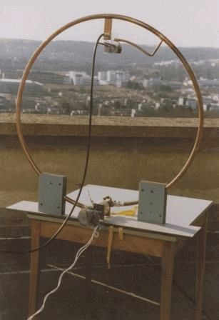
Last year, a 6-meter piece of coaxial cable fell into my hands. Its exact name: "Coaxial cable 1" flexible LCFS 114-50 JA, RFS (15239211)". It has a very low weight, instead of an external braid, a solid corrugated pipe made of oxygen-free copper with a diameter of about 25 mm, the central conductor is a copper tube
about 9 mm in diameter (see photo). This prompted me to take up the construction of a loop antenna. This is what I want to talk about.
The first antenna was built according to the DF9IV scheme. With a diameter of about 2 m and the same length of the power loop, made of a coaxial cable, it worked very well for reception, but frankly bad for transmission, the SWR reached 5-6.
The operating band for reception (at the level of -6 dB) is about 10 kHz. At the same time, it perfectly suppressed electrical interference, with a certain orientation in space, the suppression of an interfering station easily turned out to be more than 20 dB.
After some thought, I came to the conclusion that the reason for the high SWR is the use of an inner conductor with its relatively small diameter by the exciting element. It was decided not to use the inner conductor at all, leaving it in the form of an open loop.
The tuning capacitor was soldered to the outer shield. The receiving characteristics changed slightly, the minimum in the diagram became less pronounced, and the influence of surrounding objects became noticeable. But little has changed in the transmission. Further, after reading Grigorov's article once again, it was decided to remove the outer sheath from the frame cable, and coat the copper in two layers with KhV varnish (there was no more suitable one, however, it protects copper well from
oxidation). And then, finally, the first positive results appeared. SWR dropped to 1.5, about 20 local QSOs were made. The antenna was at a height of 1.5 m and could rotate in a vertical plane.
For comparison, a dipole with a total length of 42.5 m was used, made of a field wire with a symmetrical power line made of telephone "noodles" about 20 m long (a sort of "poor radio amateur" antenna), located on the roof of a 5-storey building at a height of about 3- x meters. He worked on 40 and 80 meters, fed through a symmetrical matching device - SWR on both bands = 1.0. Unfortunately, the antennas were in different QTHs and there was no
opportunity for direct comparison. But the experience of operating the dipole during the year made it possible to judge the effectiveness of the frame in the first approximation.
Now about the results: 1) SWR is about 1.5. 2) All correspondents noted a decrease (from 1 to 2 points) in the level of my signal, compared to the one with which they usually hear me on a dipole.
The rains that had begun by this time (as they say: “every other day, every day”) made further antenna experiments impossible. The main reason for the impossibility of further tests was the constant breakdowns of the tuning
condenser due to increased air humidity.
I tried, perhaps, all the options available to me, used the connection of only stator plates, connecting two KPIs in series, used capacitors from coaxial cable, high-voltage capacitors
- it all ended with one - breakdown. I did not try only vacuum capacitors, their prohibitively high cost stopped them.
And here the idea came to use the capacitance in relation to the outer screen of the unused inner conductor. An attempt to calculate the required cable length from the known linear capacitance of the cable did not lead to reliable results, so the method of gradual approximation was used.

It was a pity to cut such a wonderful cable, but "hunting is worse than bondage." Connection diagram in the figure. For power supply, a loop of a coaxial cable 2 m long was used, according to the DF9IV scheme, the supply 50-ohm cable itself was 15 m long. cable capacity.
For tuning, a butterfly-type capacitor from VHF equipment was used.
Breakdowns completely stopped, the antenna retained all the main parameters of the classic magnetic loop antenna, but became single-band.
The main results are as follows: 1) SWR of the order of 1.5 (depends on the length and shape of the feeding loop). 2) The magnetic antenna noticeably loses to the dipole (described above) with a comparable suspension height. The experiments were carried out in the range of 80 m.
I was prompted to engage in further experiments with magnetic antennas by an article by K. Rothammel in the second volume of his book devoted to magnetic frames, and an article by Vladimir Timofeevich Polyakov about a frame-beam or real EH antenna, and for understanding the processes occurring in antennas and around them, it turned out to be very useful article about near-field antennas.
After reading the article about the frame-beam antenna, I had several promising projects, but at present only one has been tested, and this will be discussed. The antenna circuit is shown in the figure, the appearance is in the photo:

All the experiments listed below were carried out in the range of 40m. In the first experiments, the antenna was at a height of 1.5 m from the ground. Various methods have been tried to connect the "dipole" (capacitive) part of the antenna to the frame, but the one shown in the figure seemed optimal to me. Here an attempt has been made to retrofit a magnetic frame emitting a predominantly magnetic component with elements emitting mainly an electrical component.
You can look at the same antenna differently: the coil included in the middle of the dipole, as it were, lengthens it to the required size, and at the same time, the rays connected in parallel with the tuning capacitor have their own capacitance (with the indicated dimensions of the order of 30 - 40 pF) and enter into the total capacitance of the tuning capacitor.
The circuit formed by the internal conductor and capacitor, in addition to approximately doubling the signal level at the reception, apparently shifts the phase of the current of the loop itself, and provides the necessary phase matching (an attempt to turn it off leads to an increase in SWR to 10 or more). Perhaps my theoretical reasoning is not entirely correct, but as further experiments have shown, the antenna works in this configuration.

Even during the very first experiments, an interesting effect was noticed - if, with a fixed dipole part, turn
frame by 90 degrees - the signal level at the reception drops by approximately 10 - 15dB, and by 180 degrees - the reception drops almost to zero. Although it would be logical to assume that when rotated by 90 degrees, the radiation patterns of the "dipole" part and the frame will coincide, but apparently not everything is so simple.
An intermediate version of the antenna was made, capable of rotating around its axis, in order to find out the radiation pattern, it turned out to be the same as that of the classical frame. The antenna was powered by the same communication loop as in the first experiments. Currently, the antenna is raised to a height of 3 meters, the beams are parallel to the ground.
About results:
1) SWR = 1.0 at 7050 kHz, 1.5 at 7000 kHz, 1.1 at 7100 kHz.
2) The antenna does not require retuning in range. With the help of the capacitors of the P-loop of the transceiver, some tuning of the antenna is possible if necessary.
3) The antenna is very compact.
At a distance of up to 1000 km, the loop and the dipole have approximately the same efficiency, and at a distance of more than 1000 km, the loop works noticeably better than the wave dipole at the same suspension height, while the loop is four times
less dipole. The radiation pattern is close to circular, the minima are hardly noticeable. Conducted about a hundred contacts with 1;2;3;4;5;6;7;9 regions of the former USSR.
An interesting effect was noted - the estimate of the signal strength in most cases remained approximately the same and at a distance to the correspondent of 300 km and 3000 km, this was not observed on the dipole. Interesting response from operators
when I reported what I was working on - amazement that you can work on it! All experiments were carried out on a homemade SDR transceiver with an output power of 100 watts.
Material taken from CQ-QRP#27
