Antenna Kharchenko: calculation and manufacturing. Wiring Diagram Loop TV Antenna Antenna Calculation Triple Square Calculator
The three-element loop antenna has a narrow main lobe and high gain. For the UHF band, in which Russian 1, 2 and 3 multiplexes are broadcast in DBV-T2 format, the dimensions of the antenna are very compact. Therefore, the Triple Square can successfully replace an indoor antenna.

The most optimal length of the reflector rib is 4% longer than the length of the vibrator rib. The dependence of the gain of the Triple Square loop antenna on the distance between the elements is shown in the figure. At B = 0.11L we have the maximum gain.

The input impedance of the antenna, as well as its gain, is also determined by the distance between the antenna elements. For example, when the distance between the reflector and the vibrator is B=0.11L, we obtain that the input impedance of the antenna is 65 ohms, and the gain compared to the half-wave dipole is 6.6 dB.

When calculating a Triple Square antenna, you can use the following formulas: B = 0.255L; P = 0.261L; D \u003d 0.247L, where L is the wavelength. The optimal distance between the elements A (B) = 0.11 .... 0.15L. The dimensions of the elements for the decimeter range (TV channels 21 - 80) of the Triple Square antenna are shown in the table.
| Channels | D (mm) | H (mm) | R (mm) | A (mm) | B (mm) | W (mm) |
| 21 - 26 | 134 | 158 | 193 | 57 | 98 | 152 |
| 27 - 32 | 122 | 144 | 176 | 61 | 89 | 139 |
| 33 - 40 | 110 | 131 | 160 | 55 | 80 | 126 |
| 41 - 49 | 99 | 117 | 143 | 50 | 72 | 112 |
| 50 - 58 | 89 | 105 | 129 | 45 | 69 | 102 |
| 59 - 68 | 81 | 96 | 113 | 41 | 59 | 92 |
| 59 - 80 | 73 | 86 | 106 | 37 | 53 | 83 |
Frequency grid of television channels in the city of Zhukovsky, Moscow Region.
Therefore, in this locality, an antenna designed for television channel 30 (carrier frequency 546 MHz) will be optimal.
The Triple Square loop antenna can be improved by adding three more elements. The gain of the modified antenna increases significantly, which will give it an advantage when used both indoors and outdoors. The design of the antenna is shown in the figure,

sizes - in the table.
| Channels | W | G | F | D | IN | R | BUT | B | AND | TO | L | W |
| 21… 26 | 68 | 90 | 112 | 134 | 158 | 193 | 67 | 98 | 55 | 43 | 31 | 150 |
| 27 … 32 | 56 | 79 | 100 | 122 | 144 | 176 | 61 | 89 | 49 | 37 | 25 | 138 |
| 33… 40 | 44 | 66 | 88 | 110 | 131 | 160 | 55 | 80 | 43 | 31 | 19 | 124 |
| 41 … 49 | 33 | 55 | 77 | 99 | 117 | 143 | 50 | 72 | 38 | 27 | 16 | 109 |
| 50… 58 | 24 | 45 | 67 | 89 | 105 | 129 | 45 | 69 | 34 | 21 | 12 | 99 |
| 59 … 68 | 17 | 38 | 59 | 81 | 96 | 113 | 41 | 59 | 30 | 18 | 8 | 96 |
| 69… 80 | 10 | 31 | 52 | 73 | 89 | 106 | 37 | 53 | 26 | 14 | 4 | 81 |
For manufacturing, you can use a wire made of copper or brass with a diameter of 3 ... 5 mm. The wire is sequentially bent in the shape shown in the figure, the joints are soldered. For greater structural strength, before soldering, the joints can be pulled together with a thin copper wire.
The antenna cable is soldered at points "a" and "b". At point "c" the cable sheath is connected to the material of the antenna.
The popularity of the Internet among the population is constantly growing. However, many people live in places where the signal is very weak or non-existent. In this regard, the problem of increasing the power and quality of Internet reception is very acute. Slow speed takes a lot of time and does not give the desired result. Therefore, an external Kharchenko antenna often comes to the rescue, designed in the form, the material for which is a thick copper wire. The square connection between themselves occurs in places of open corners, where the television cable is connected.
Such an antenna requires an accurate calculation for digital terrestrial television. To improve directivity, some designs may have a grating or solid screen of conductive material. Such a biquad antenna allows you to solve many problems with signal reception and Internet speed. Home-made designs, including various types of Kharchenko antennas, are relatively easy to manufacture and include metal and plastic parts, as well as elements from other materials, connected in different ways. Similar designs are easily made on their own, including the Kharchenko antenna for TV with their own hands.
Harchenko antenna for modem
Currently, many users are striving to increase the speed of their mobile Internet. This problem is especially acute for those who live at a considerable distance from the base station, using the Internet at a very low speed. In such situations, the best way out is the Kharchenko antenna for a 3g modem with your own hands, which is quite easy to make at home.
This frame structure has been known as the UHF antenna since the 60s of the last century. It has a zigzag frame configuration, which makes the device very efficient.
The system consists of two square elements. In order to calculate the antenna for a 3g modem at a frequency of 2100 MHz, the size of each side of the square should be 53 mm. The whole structure is made in the form of an interlocked structure, which includes two diamond-shaped figures with internal angles of 1200. This is done in order to reduce the internal resistance of the device. The connection of rhombuses is carried out by soldering. The high-frequency cable is also soldered here.
More accurate data can be obtained using the online calculator for calculating the Kharchenko antenna, in which you just need to enter the necessary initial data.
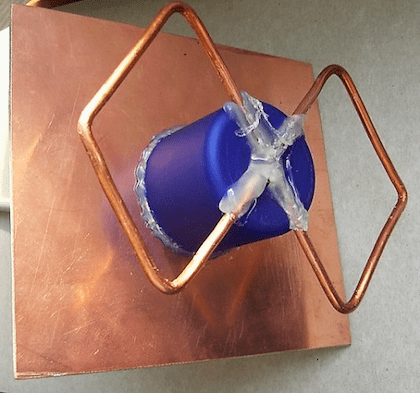
To increase efficiency, the device can be used in conjunction with a reflector. Usually this part is a metal plate, and foil textolite is the most suitable material for its manufacture. In this case, the antenna includes determining the distance between the receiver and the reflector. After calculations and procurement of materials, a do-it-yourself Kharchenko antenna for the modem can be made.
The parts are connected to each other with the help of hot glue. You can fix the desired distance between the elements using any object with the most suitable dimensions. Then the antenna is connected to the device. Since the modems do not have connectors for connecting external antennas, they are simply wrapped with wire, which is then connected via a cable to the receiving device. If necessary, the Kharchenko antenna for a 4g modem can be made according to the same scheme.
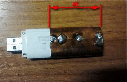
Upon completion of the assembly, at the opposite end of the cable that will be connected to the modem, you need to assemble the so-called matching device, which is provided specifically for such devices. For this purpose, copper foil is used, the same as in printed circuit boards. The performed antenna calculation for a 4g modem is the same as in the previous version.
If there is a connector for an external antenna, the cable is connected using a special adapter. After all connections, the antenna for the modem is considered ready for use. Setting the signal reception for 4g is carried out experimentally, by slowly rotating the structure around the axis until the clearest signal is obtained. Signal quality is determined by the number of dashes on the icon displayed on the computer or mobile phone.
Antenna Kharchenko for digital TV
For the operation of digital television, a range of decimeter waves is used. Therefore, before designing, Kharchenko antennas for DVB t2 should be made in order to maximize signal reception.
The design itself looks quite compact, it is made in the classic version of two rhombuses, as a result, a zigzag antenna without a reflector is obtained. Any conductive material can be used as a base, for example, a copper or aluminum conductor with a diameter of 1-5 mm. Tubes, strips, corners, profiles, etc. are also suitable. Copper wire 3 mm thick is best suited for these purposes. It is very easy to bend, level and solder. Further, it must be made in a certain sequence. TV cable resistance should be approximately 50-75 ohms.

The quality of a digital signal does not depend on distance, as it happens in analog television. In this case, when the TV antenna is working normally, the signal normally enters the TV receiver, but if there are failures, then there will be no signal at all. Accordingly, there will be no image. If there is a signal and it is normally received, then the image will be of the same quality on all channels. This factor must be taken into account when performing for digital TV, although individual settings may be different for a particular region.
Kharchenko's television antenna itself is made in a certain sequence:
- First you need to measure a piece of wire with a total length of 112 cm and bend it, observing the dimensions of the sections alternately 13 and 14 cm.
- After all the bends, two ends are formed, which must be cleaned to a distance of 1.5-2 cm. Loops are made at the ends and fixed to each other. The joints are completely soldered. Then, the central core is soldered to one of the joints, and the braid to the other. The result is a finished antenna or a double square.
- A biquad TV antenna requires a TV cable of approximately 3 meters. From the side of the antenna, it is stripped by 2 cm, and from the side of the plug - by 1 cm. The plug can be chosen at your discretion. It, like the wire, needs to be cleaned with a needle file or some kind of sharp object. Thus, Kharchenko's zigzag antenna for digital TV is almost ready for use.
- After soldering, all joints should be filled with hot glue from a gun. While the glue has not cooled down, its excess must be collected. It turns out at the same time reliable and elastic connection. On the antenna itself, the soldering points are also filled with glue.
Kharchenko antenna for phone
An external directional antenna can significantly increase the capabilities of a mobile phone and improve the quality of communication when a subscriber is in a remote area. It is not always possible to find the most suitable option on sale, so the best way out is the Kharchenko antenna for cellular communications, made from improvised materials with your own hands.

The most affordable option is the standard design discussed above. Such an antenna should be sized according to the specific operating conditions. All necessary materials are sold in the hardware store. The simplest designs can be directly connected to the cable and do not require any special settings.
First of all, it is necessary to stock up on copper wire, with a diameter of 2-3 mm. You can take an insulated wire and remove the insulation from it. If connections are to be made without soldering, special F-type antenna connectors and connectors will be required. When it is planned to connect two Kharchenko antennas in parallel, you may need a reflector, which can be tin or aluminum. Joints are insulated with heat shrink tubing or electrical tape. Soldering requires a soldering iron.
Copper wire, prepared in advance, is bent and turns into a zigzag frame, which is two rhombuses. The sides of each of them are 80 cm long, and the total distance between opposite corners will be 226 cm. Next, the antenna calculator determines the connection point of these diamonds as the junction with the cable. A piece of cable, 50 cm in size, is soldered to this point, and an F-type connector is screwed to its opposite end. Next, the main cable of the required length is connected to the connector.

In some cases, the calculation of the Kharchenko antenna online involves the installation of a reflector that significantly enhances signal reception in a certain area. The design is the same as the antenna for T2, when the lower end of the frame and the reflector are connected to each other through the cable braid. For this purpose, a bolt 50 mm long is additionally screwed into the reflector, to which an F-type connector is attracted with a tie. Beforehand, a cable and a frame located at a distance of more than 40 mm are soldered to this connector. Thus, the Kharchenko antenna for a mobile phone, made independently in the simplest version, is ready for use.
For direct connection of the receiving device with a mobile phone, a pigtail is used, which is a special wire. One end is connected to the antenna cable, and the other end is connected to the phone's antenna jack using a connector. In this case, there is no problem to calculate the antenna and no separate settings are required, it is enough just to position the antenna in the most optimal way, focusing on the quality of the received signal. It is recommended to install the mast with the receiving device as close to the house as possible, preferably near the window, in order to minimize the length of the cable.
Many summer residents do not want to buy good antennas for their houses, since they do not live in them permanently. In order to watch TV programs while resting from gardening, they often use devices with a characteristic impedance of 75 ohms. The choice in favor of homemade double square antennas is due to the low cost of consumables, as well as the speed of fabrication.
What you need to make a double square antenna
Today, analog TV has been replaced by digital TV. Thanks to new technologies, people have been able to watch programs in excellent quality, and the number of available channels has significantly increased. To connect to digital TV, it is enough to have a good TV, a decoder and accessories for installation. To receive a video signal on your equipment, you must have a double-square decimeter antenna. It makes no sense to buy it, since, having a minimum of materials at hand, you can make the device yourself in a matter of minutes.
The double square antenna in appearance resembles a pair of interconnected rhombuses. Despite the primitive design, it will receive a signal quite well. For its manufacture, you can use any material that can conduct current, for example, a corner, a metal strip, wire, rods, tubes. In order to maximize the signal, a reflector, made, for example, of foil, should be placed behind the paired squares.
If it is decided to do all the work with your own hands, then you need to prepare the following components for such an antenna:
- WiFi adapter. A piece of cable (high-frequency) designed to connect Wi-Fi. Its resistance should be within 75 ohms or 50 ohms.
- A wire made of copper, the cross-sectional size of which varies from 1.5 mm to 3 mm. It bends well, so it will be used for wiring. If copper wire cannot be found, steel material can be used, the cross section of which varies from 2mm to 5mm.
- Sheet of textolite (foil), size 100mm x 120mm. It can be replaced with a sheet of getinaks, the same size.
- Plug.
- Raw materials for spacers: wooden planks, fiberglass, duralumin tubes.
- Tools (hammer, soldering iron, sandpaper, etc.).
- Pole for fixing the antenna on the wall of the house or on the roof.
- Fasteners.
The double square antenna has a simple design, including: a reflector and an active element. For their manufacture, in most cases, copper wire is used.
In the break of the active element, located below, a cable (coaxial) is connected, the wave impedance of which is 75Ω. The reflector gap is a two-wire open line that continues the frame line. Between the wires there is a distance of 150mm - 200mm, as well as a jumper sliding along the line, designed for adjustment.
The antenna elements are stretched over spacers, for the manufacture of which it is best to use insulating materials, for example, pine planks, bamboo sticks, fiberglass.
Many experts recommend using duralumin pipes equipped with insulators along the edges for these purposes. In this case, the vertical struts are made from solid raw materials, and the horizontal elements are separated by insulating inserts. For them, you can use reinforced fluoroplastic, fiberglass, etc. The main thing is to fulfill the main condition. Each of the four spacers, arranged horizontally, must consist of insulated elements of equal dimensions.
Do I need to do calculations?
If a person independently decided to make a double square antenna to receive a digital signal, he does not need to calculate the wavelength. Experts recommend that people, in order to receive the maximum number of signals by devices, make designs more broadband.
In the case when the master seeks to make the antenna according to all the rules, he can perform the calculations.
To do this, he needs certain data:- You can find out the size of the side of the square in this way. The wave on which the signal is broadcast is determined. This number is divided by 4.
- You can find out what ideal distance should be between the 2 parts of the device in this way. The inner elements are shorter, and the outer sides of the diamonds are slightly longer.
Antenna double square fabrication
After the master has found out what dimensions of the double square antenna should be used, he can begin to manufacture it.
This process includes several stages:- First of all, you will have to carefully strip the cable from both sides. The end that will be attached to the structure itself should be cleaned so that the wire comes out of the insulation by about 2 cm. If the bare tip is larger, then the excess should be cut off.
- The foil, which will act as a reflective screen, and the braid must be twisted into a bundle.
- As a result, the master will have two conductors that need to be tinned.
- The second edge of the cable (1 cm) is taken and a plug is soldered to it. Those places where soldering will be carried out must be treated with a solvent or alcohol. After that, you need to clean up with a file or sandpaper. A plug is put on the prepared cable with a plastic part, soldering is done.
- At the next stage, you will have to solder the monocore to the plug output (central), and the stranded twist to the side.
- The grip is crimped around the insulation. This is also done in the manufacture of a triple square antenna.
- A tip made of plastic is screwed on. Experts recommend filling the cavities with a non-conductive sealant or glue.
- The plug design is quickly assembled, until the adhesive mixture has hardened (its excess is removed).
- Do-it-yourself connection of two elements is carried out: a frame with a cable. Due to the fact that during the manufacturing process of the antenna no binding was made to a specific channel, it is necessary to solder the cable to the midpoint of the frame. As a result, it will be possible to increase the bandwidth of the design, which will receive more channels.
- The second prepared end of the cable must be soldered in the center to the two sides, which were previously stripped and tinned.
- At this stage, the process of manufacturing the active frame structure has been completed, now we move on to checking and installing the antenna.
If the owner of a country or country house plans to get a higher gain of the received digital signal, he should make a triple square antenna.
To do this, it is necessary to identify the frequencies according to the same principle, calculate the main parameters. For a UHF antenna, a triple square will require more consumables, since it will be necessary to create an additional frame - a smaller director.
Important! To correctly calculate the triple square antenna for digital television, you can use the online calculator. It is necessary to enter the following data into it: frequency, type of wire, MHz. After clicking on the "result" button, the program will automatically carry out the calculations and display the numbers in a special window.
Double square antenna test
Once an antenna design has been created, it should be tested. Without fail, the master must configure the emitter, thanks to which it will be possible to watch programs in the highest possible quality for such conditions.
When conducting tests, several nuances should be taken into account:- The directional pattern of the structure will mow in the absence of a device that provides symmetry.
- If the sides of the square are excited in phase, then the polarization of the email. field to the plane of the structure is carried out perpendicularly.
- You can compensate for the reactive component of the antenna (after tuning the antenna) when setting up the bridge (balancing), lengthening or shortening this element.
- If the antenna impedance under the cable is higher, then this will have a positive effect on the gain. That is why the design should use a coaxial cable not 50 Ohm, but 75 Ohm.
- The antenna should be placed in a protective case, which will prevent flooding, snow sticking, and icing. For these purposes, you can use a 5l plastic eggplant.
- During the test, the second square of a laptop or PC with wi-fi connections should not be near the antenna. As soon as the design is included in TV equipment, it is possible to catch these signals using computer technology. The highest quality wi-fi points will be detected when installing the antenna on the roof.
- The tuner is tuned and the video and sound quality is checked.
Conclusion and Features of Double Square Antenna
This design is directional. If the user rotates it 360 degrees, he will be able to catch a variety of signals. Owners of country houses and cottages who do not use reflective screens should be aware that in this case the signal quality will decrease by at least 30%. Its functions can be replaced by a satellite dish hat. A double square structure should be attached to the location of the head. Thanks to such manipulations, it will be possible to maximize digital signals without a reflective screen.
Television is in every home today. With the development of technology, the quality of television signals and the methods of their transmission are changing. And if yesterday antediluvian analog broadcasting was used, today exclusively digital broadcasting is being persistently discussed.
On the territory of Russia, the state-owned company RTRS is engaged in television and radio broadcasting. Since 2012, by government decree, DVB-T2, the multiplex digital broadcasting standard, has been recognized as the unified standard for digital terrestrial television. The RTRS company, as the only broadcast operator, offers two multiplex packages at once (RTRS-1 and RTRS-2) for free viewing. All you need is a modern receiver-antenna, one of the options for which we propose to do with your own hands today.
The basis of this homemade product is the development of engineer Kharchenko K.P., who proposed similar antennas for the decimeter range (DCV), popular in the 90s of the last century. This is a similarity of aperture antennas, based on which the feed is in the form of a zigzag shape. The signal is accumulated by a flat reflector, which is at least 20% larger than the vibrator.
The television signal is transmitted in waves with horizontal polarization. In a simplified form, such an antenna consists of two horizontal loop vibrators connected in parallel, but disconnected at the connection point of the feeder (cable). Overall dimensions are given on the basis of Kharchenko's article "Antenna of the DCV range", and are calculated according to the proposed formulas. According to this technology, such antennas can be calculated even for a weak signal of about 500 MHz.


What you need to assemble the antenna
Materials:- Barbecue grill;
- Aerosol paint for cars;
- Solvent or acetone;
- A set of drills for a conventional drill;
- Coaxial TV cable - no more than 10 m;
- Half a meter of PVC pipes XV, diameter - 20 mm;
- Metal dowels for drywall;
- Copper wire for the antenna vibrator, core diameter - 2-3.5 mm;
- Two thin metal plates.
- Soldering iron powerful 100 W;
- Screwdriver with nozzles;
- Hot glue gun;
- Pliers, hammer, wire cutters;
- Paint knife, tape measure, pencil.

Let's start making an antenna
Making a frame vibrator
We measure the required length of the copper wire with a margin of about 1 cm. You can also use a copper or aluminum tube with a diameter of up to 12 mm.

We clean the copper core from insulation, and level it with a hammer on a hard surface. Mark the middle and make a 90 degree bend. The most accurate way to do this is in a vise, slightly pressing the copper core and leveling it with a hammer.


According to our calculations, the sides of the squares will be 125 mm. We mark them with a tape measure, and make bends.


From one end we bite off a small fragment with side cutters, making the tip pointed at 45o. After bending the second square, we carry out the same procedure, biting off the final end of the core. Squares for this can be slightly straightened.


On the middle bends of the squares, we achieve a distance of 10-12 mm. At the ends we make shallow cuts with a needle file. This will help us pull both free ends together and secure them with thin copper wire.


Using liquid rosin or flux, we tin the middle bends with a soldering iron. This must be done on all sides of the copper core of the vibrator.


We clean the coaxial cable by 4-5 cm. We twist the braid or outer conductor into a single wire, wrap it around one of the bends. We solder it to the copper core with a soldering iron.


We clean the insulation of the inner conductor, and also wrap it around the next bend of the frame. You need to solder it carefully while holding the insulation with pliers, because it can simply shift from the center due to temperature. We first heat the frame in the soldering zone, and only then the conductor itself.


We fix the coaxial cable connection with a nylon tie, degrease it with a solvent and isolate the soldering points with hot glue using a gun. You can correct the defects of the resulting cast form of glue with a hairdryer.


Cooking reflector
We use an inexpensive barbecue net as a reflector or reflective screen. This is a good material, since even steel samples of such products are covered with a corrosion-resistant anodized coating, not to mention stainless steel. A heat exchanger from a modern refrigerator or a drying rack for dishes is also suitable. The main thing is that this element, if possible, does not rust in the air.The reflector grid should be larger than the vibrator frame, but need not be symmetrical. We cut off the handles from the lattice, they will be superfluous in our design.


We place the antenna frame in the middle of the reflector, and mark the places of its fastening. For fastening, you can use two plates of any metal. We bend them along the grid, and drill holes with a diameter of 5 mm.


Assembling the antenna
We cut off two pieces of PVC pipes 75 mm long, and screw them into the end of each with a self-tapping screw, cutting off the protruding parts. At drywall dowels, we break off the pointed tips, and screw them into the opposite end of the tubes.


We fasten both PVC racks to the slats on the reflector with self-tapping screws. We tin the frame at the ends that fit the racks for better heat transfer.


On the racks we mark the height of 68 mm, and put at risk. We heat the ends of the frame with a soldering iron, and solder them into the racks to the desired marks.
Loop Antennas
An ordinary loop vibrator can be transformed into a square frame, the perimeter of which is approximately equal to the wavelength (Fig. 1).

Rice. 1 Transformation of the loop vibrator into a square frame.
Antennas of this type are called loop or loop antennas. For receiving television programs, two-element and three-element loop antennas are most often used, which are also called “double square” and “triple square”. These antennas are characterized by simple design, rather high gain and narrow bandwidth.
Narrowband antennas provide frequency selectivity compared to broadband antennas. Due to this, interfering signals from other television transmitters operating on channels close in frequency cannot penetrate the input of the television receiver. This is especially important in weak signal conditions. Often there is a need to receive a weak signal from a remote transmitter in the presence of a nearby powerful transmitter of another channel. Under such conditions, the frequency selectivity of the television receiver may not be enough. In addition, an intense interfering signal, entering the first stage of the receiver (or antenna amplifier), leads to cross-modulation of the useful signal by the interfering signal. In subsequent cascades, it is no longer possible to get rid of this. Therefore, narrow-band antennas should be used in such cases.
A two-element loop antenna is shown in fig. 2. The frames of the antenna are square in shape, and at the corners they can have roundings of an arbitrary radius, not exceeding about 1/10 of the side of the square. The frames are made of a metal tube with a diameter of 10-20 mm for antennas of channels 1-5 or 8-15 mm for antennas of channels 6-12. Metal can be any, but copper, brass or aluminum is preferable.

Rice. 2. Two-element loop antenna.
For the decimeter range, the frames are made of a copper or brass rod with a diameter of 3-6 mm. The upper arrow connects the middle of both frames, and the lower one is isolated from the vibrator frame and is attached to a plate made of textolite or organic glass. The ends of the vibrator frame are attached to the same plate with screws and nuts, for which its ends can be flattened. Arrows can be made of metal or insulating material. In the latter case, there is no need to specifically connect the frames to each other. The mast must be wooden, at least its upper part. The metal part of the mast should end 1.5 m below the antenna. The antenna frames are positioned relative to each other so that their geometric centers are on a horizontal straight line directed to the transmitter.
The cable is connected to the ends of the vibrator frame using a quarter-wave short-circuited balancing loop, which is made from the same cable. The loop and cable must approach the antenna vertically from below, the distance between them must be constant along the entire length of the loop, for which textolite spacers can be used. It is also possible to fasten the cable and the cable to the insulating plate to which the lower boom and the ends of the vibrator frame are attached. At the same time, small holes are drilled in the plate, and the cable and cable are tied to it with a nylon fishing line. The use of metal fasteners is undesirable.
To ensure rigidity, a train can be made of two metal tubes connected by their upper ends to the ends of the vibrator frame. In this case, the cable is passed inside the right tube from the bottom up, the cable braid is soldered to the right, and the central core to the left ends of the vibrator frame. The loop tubes in the lower part are closed with a jumper, by moving which you can adjust the antenna to the maximum received signal.
The dimensions of two-element loop antennas recommended for meter television channels are shown in Table 1.
Table 1. Dimensions of two-element loop antennas of meter waves, mm
Rooms channels |
||||||||||||
1450 |
1220 |
|||||||||||
1630 |
1370 |
1050 |
||||||||||
1500 |
1260 |
B \u003d 0.26L, P \u003d 0.31L, A \u003d 0.18L, where L - the average wavelength of the received frequency channel, which is given . The length of the loop for this antenna is taken from table 1(parameter W).
The dimensions of two-element loop antennas for decimeter waves are given in Table 2. Since in this range the antenna bandwidth covers several frequency channels at once, the dimensions are given not for one channel, but for a group of adjacent frequency channels.
The double-square loop antenna has a higher gain (by about 1.5 dB) compared to the two-element wave channel antenna. This applies to antennas having the same length. Antenna gain is largely determined by the distance between antenna elements. The optimal distances from this point of view are within 0.12 .... 0.15L.
Table 2. Dimensions of two-element loop antennas of decimeter waves, mm
| Channels | IN | R | BUT | W |
| 21- 26 | 158 | 170 | 91 | 152 |
| 27-32 | 144 | 155 | 83 | 139 |
| 33-40 | 131 | 141 | 75 | 126 |
| 41-49 | 117 | 126 | 68 | 113 |
| 50-60 | 105 | 113 | 60 | 101 |
The design of a three-element loop antenna “triple square” is shown in fig. 3.

Rice. 3. Antenna "triple square".
The antenna contains three square frames, the director and reflector frames are closed, and the vibrator frame at points a - a "is open. The frames are located symmetrically, so that their centers are on a horizontal straight line directed to the television center, and are attached to two arrows in the middle of the horizontal The upper boom is made of the same material as the frames Experience has shown that the antenna works better if the lower boom is made of insulating material (for example, PCB rod) The upper boom is soldered to the frames, and the lower boom can be attached to the frames with the connection points are filled with epoxy resin.The antenna is attached to a mast made of insulating material.As in the case of the "double square", a quarter-wave short-circuited stub is used for balancing, made from a piece of the same cable.
There is also a simple design of a three-element UHF loop antenna from one piece of thick wire, shown in fig. 4.
At points A, B and C, the wires must be soldered. Instead of a stub made from a piece of coaxial cable, a quarter-wave short-circuited bridge of the same length as the stub is used. The distance between the wires of the bridge remains the same - 30 mm. The design of such an antenna is quite rigid and there is no need for a lower boom. The cable is tied to the right wire of the bridge with

Rice. 4. Antenna option “triple square”.
outside side. When the cable approaches the vibrator frame, its braid is soldered to point a, the central core to point b. The left wire of the bridge is fixed on the mast. It is only necessary to pay attention to the fact that neither the cable nor the mast is located in the space between the wires of the bridge. You can also get acquainted with the description of the design of a three-element antenna from one piece of wire. , with the design six-element - .
The input impedance of the antenna, as well as its gain, is also determined by the distance between the antenna elements. Figure 5 shows the dependences of the gain and input resistance on the distance between its elements.
For example, with a distance between the reflector and the vibrator of 0.11L, we obtain that the input impedance of the antenna is 65 Ohm, and the gain


Rice. 1.5. Dependences of the gain and input impedance of the loop antennas on the distance between the elements (top figure: 1 - “triple square”, 2 - “double square”; bottom figure: 1 - single antenna of the “square” type, 2 - “double square”, 3 - distance S = 0.11L corresponds to the maximum gain).
compared to a half-wave dipole is 5.5 dB (for a “double square”) and 6.6 dB (for a “triple square”). It should be noted that the gain values of loop antennas given in the popular literature are greatly overestimated and reach 14 dB.
Two-element and three-element loop antennas have a rather narrow main beam and therefore must be carefully oriented.
The antenna is tuned by changing the length of the cable connected to the reflector. The most optimal reflector length is 4% longer than the vibrator length.
When calculating an antenna of the “triple square” type, you can use the following formulas: B = 0.255L; P \u003d 0.261L; D \u003d 0.247L, where L is the wavelength. The optimal distance between the elements A \u003d 0.11 .... 0.15L.
Studies have shown that switching from a two-element "square" antenna containing a vibrator and a reflector to a three-element antenna leads to a gain in gain of 1.7 dB. A similar procedure for a wave channel antenna gives a gain of 2.7 dB. It should also be noted that the triple square antenna has a narrower bandwidth than the double square antenna. The dimensions of the “triple square” antennas for the meter and decimeter wave bands are given in tables 3 and 4.
For sufficient strength, the frames and the upper boom of the meter-wave antenna are made of a tube with a diameter of 10 ... 15 mm, and the distance between the ends of the vibrator frame is increased to 50 mm.
Table 3. Dimensions of three-element loop antennas of meter waves, mm
Channel numbers |
||||||||||||
1255 |
1060 |
|||||||||||
1485 |
1260 |
|||||||||||
1810 |
1530 |
1190 |
1080 |
|||||||||
